39
Installation
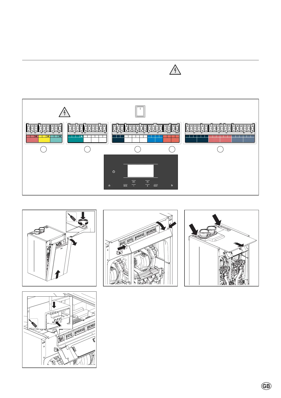
Electrical connection
The boiler has 4 socket blocks for all electrical connections:
1. High voltage supply (230V)
2. Voltage free switches (230V relays)
3-4. Low voltage sensors and I/O
5. CommunicationbusforcascadedTRIGONLPLUSboilers
Electrical connections above can be reached following the steps below:
1. Remove the front panel.
2. PressbothexternalsidesofthecontrolunitHMI(E)androtatethedisplay(F).
3. Slidethetoppaneltothefrontandusetheentranceatthebackoftheboiler
toinsertthecables(H1forhighvoltagecable,H2forlowvoltagecable).
4. Connectthecablewithscrewconnectorsalreadyinthesocketblocks.
(2x)(2x)
0
PWM
L1 N L2 1.1 1.2 2.1 2.2 3.1 3.2
3 WV/DHW pump (AC) VFR3
VFR2VFR1
Output Output
Output Output
L N L N L N
Input Output Output
PWM 0-10V GND 5VNTC 5VNTC 5VNTC 5VNTC 5VNTC
Signal
GND
Signal
GND
MO1 (0-10V output) MTS1 (T10) MTS2 MTS3
NTC 7
(outd. sensor)
NTC 3 (DHW/
Tank sensor)
eBus eBus
Input OutputOutput Input Input Input Input Input
GNDPWM 0-10V 24VSignalGND 24VSignalGND Signal 24VGND 24V 5VSignalGND GND Signal
PADIN 3 PADIN 4PFDIN 1 PADIN 1 PADIN 2MO2 (0-10V output)
InputInput Input InputOutput Input
1 2 5 4
A
C
B
D
E
G
H1
H2
J
I
F
Caution:
After removing the panels 230V
partscabbereached.
Electrical connections are only to
becarriedoutbyqualiedsta.
1
2
3
4
3