6-24
Logic Level input type:
a) set the configuration switches as: S1=OFF, S2=OFF, S3=ON, S4=ON, S5=ON, S6=ON;
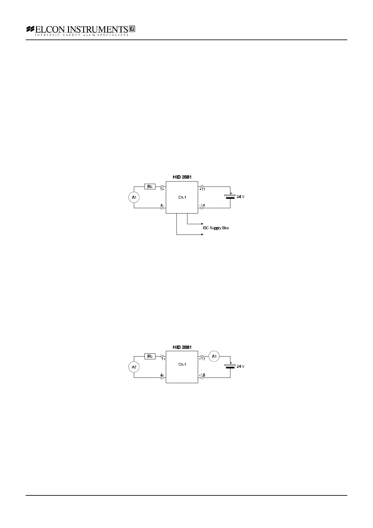
b) connect the power supply at the termination board supply terminals; feed the supply voltage at the input
terminals; connect the multimeter A1 (current mode), in series with the resistor box Rc, at the output terminals; set
the supply at 24 V and switch it on; the green power LED must go on;
c) set the resistor box to 300 Ω; the output current must be within 46 and 54 mA; the yellow status LED must be on
and the red fault LED must be off;
d) set the resistor box to 0 Ω (output short-circuit); both the yellow status and the red fault LED must be on.
e) disconnect the resistor box (output open-circuit); both the yellow status and the red fault LED must be on.
f) re-connect the resistor box at the output terminals and set it to 300 Ω; the yellow status LED must be on and the
red fault LED must be off;
g) disconnect the input terminals voltage (input open); the output current must be within 3 and 5 mA; both the
yellow status and the red fault LED must be off;
h) set the resistor box to 0 Ω (output short-circuit); the yellow status LED must be off and the red fault LED must
be on.
i) disconnect the resistor box (output open-circuit); the yellow status LED must be off and the red fault LED must
be on.
Loop powered mode:
a) set the configuration switches as: S1=ON, S2=ON, S3=ON, S4=ON, S5=OFF, S6=OFF;
b) connect the power supply, in series with the first multimeter A1 (current mode), to the unit “Loop power” input
terminals; connect the second multimeter A2 (current mode), in series with the resistor box Rc, at the output
terminals; set the supply at 24 V and switch it on;
c) set the resistor box to 300 Ω; the output current must be within 46 and 54 mA; both the green power and yellow
status LED must be on; the red fault LED must be off;
d) set the resistor box to 0 Ω (output short-circuit); the green power, the yellow status and the red fault LED must
be on.
e) disconnect the resistor box (output open-circuit); the input current must be < 30 mA; the green power, the yellow
status and the red fault LED must be on;