9-11
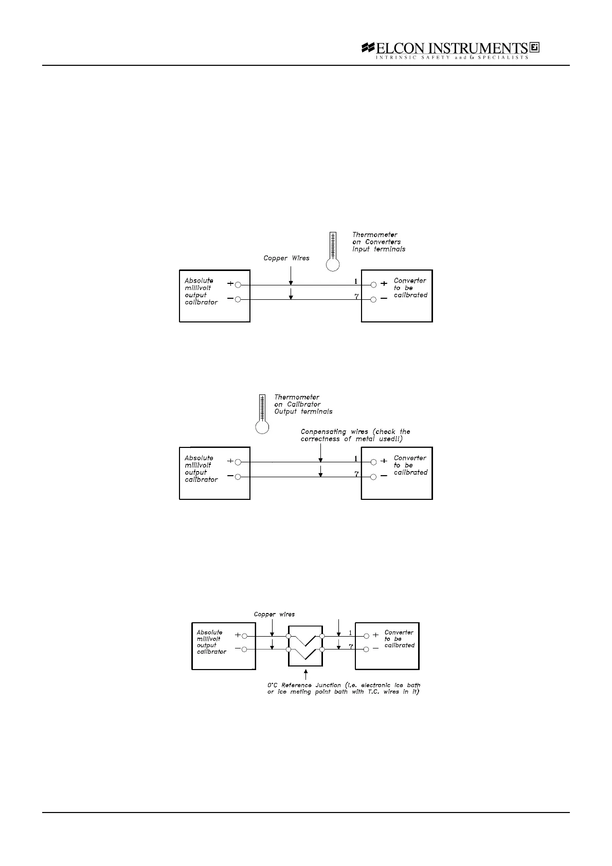
9.2.3.1 Copper Wires Calibration
To set a calibrated signal at low (L) or high (H) end of scale:
Look on the pertinent Thermocouple (TC) table for the desired temperature; read the corresponding e.m.f. voltage
Vt(L) or Vt(H).
Using a thermometer, read the input connection cable temperature taken at the converters input terminals.
Use the TC table to obtain the corresponding Reference Junction potential Vr (the same supplied by the
instruments RJ. compensating circuit).
Compute the compensated potential Vc:
Vc(L)= Vf(L) - Vr or Vc(H)= Vt(H) – Vr
Set the computed value on a absolute millivolts calibrator.
9.2.3.2 Compensating Wires Calibration
The procedure is a seen in 9.2.3.1. In this case the temperature reading is taken at the calibrator end because
there Reference Junction compensation takes place.
9.2.3.3 0 °°C Reference Junction Calibration
With this configuration the Reference Junction is held at 0°C (melting point of ice or electronic/electric device
simulating the same effect).
The instruments compensates the Reference Junction at its terminals.
The values Vt(L) and Vt(H) can be read directly from the TC table (see paragraph 9.2.3.1) as calibrating signal
Vc(L) or Vc(H) since the millivolt values are referred to 0°C Reference Junction.