6-5
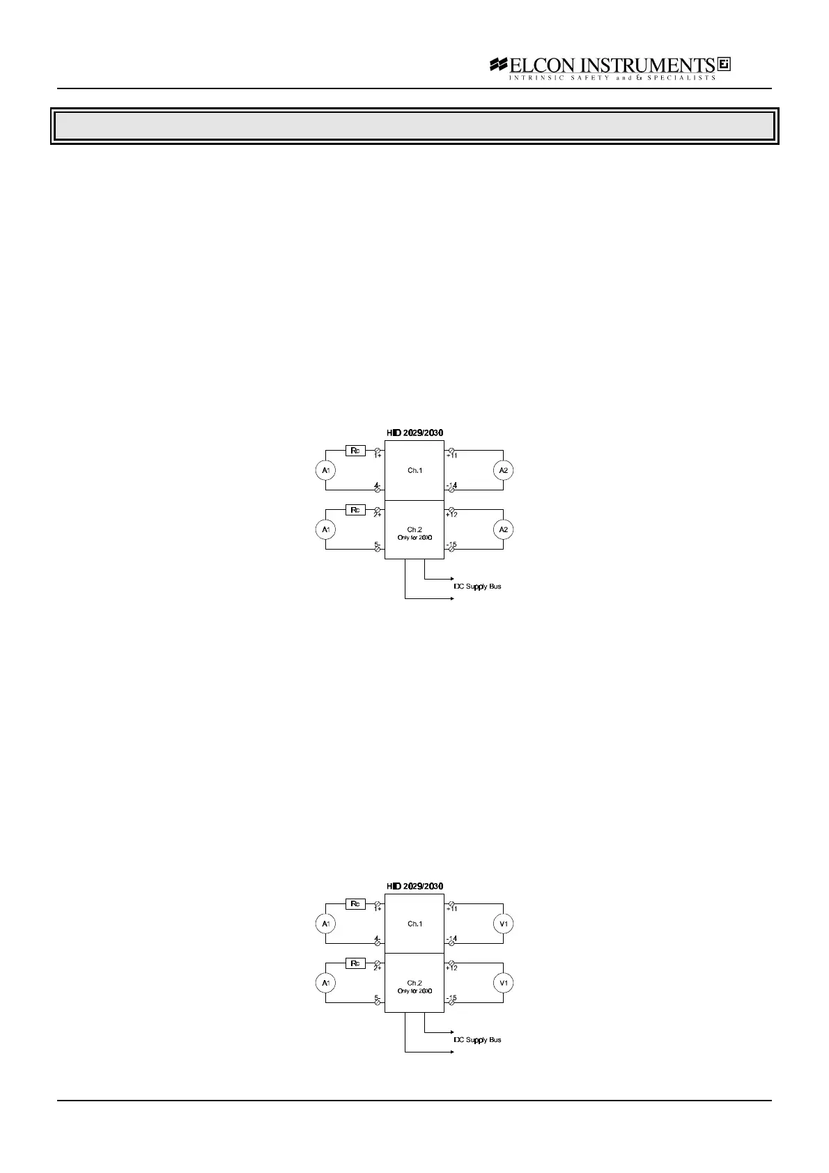
6.2.3 HiD 2029/2030
For these isolators, the output type is configurable: 4-20 mA or 1-5 V. Two distinct check procedures are therefore
presented.
Current output:
a) connect the power supply at the termination board supply terminals; connect the first multimeter A1 (current
mode) at the input terminals, in series with the resistor box Rc; connect the second multimeter A2 (current mode)
at the output terminals; set the supply at 24 V and switch it on; the green power LED must go on;
b) set the resistor box to 780 Ω; the input current must be within 19.50 and 20.50 mA; the output current must be
the same, with an error lower than 20 µA; the red Fault LED must be off
c) set the resistor box to 5 KΩ; the input current must be within 3.50 and 4.50 mA; the output current must be the
same, with an error lower than 20 µA; the red Fault LED must be off
d) set the resistor box to 1500 Ω; the input current must be within 11.50 and 12.50 mA; the output current must be
the same, with an error lower than 20 µA; the red Fault LED must be off
e) set the resistor box to 0 Ω; the (short-circuit) input current must be within 25 and 30 mA; the output current must
be the same, with an error lower than 100 µA; the red Fault LED must be on
f) disconnect the resistor box; the (open-circuit) output current must be lower than 1 mA; the red Fault LED must be on
Voltage output:
a) connect the power supply at the termination board supply terminals; connect the first multimeter A1 (current
mode) at the input terminals, in series with the resistor box Rc; connect the second multimeter V1 (voltage mode)
at the output terminals; set the supply at 24 V and switch it on; the green power LED must go on;
b) set the resistor box to 780 Ω; the input current must be within 19.50 and 20.50 mA; the output voltage must be
equal to the input current multiplied by 250 Ω, with an error lower than 10 mV; the red Fault LED must be off
c) set the resistor box to 5 KΩ; the input current must be within 3.50 and 4.50 mA; the output voltage must be
equal to the input current multiplied by 250 Ω, with an error lower than 10 mV; the red Fault LED must be off
d) set the resistor box to 1500 Ω; the input current must be within 11.50 and 12.50 mA; the output voltage must be
equal to the input current multiplied by 250 Ω, with an error lower than 10 mV; the red Fault LED must be off
e) set the resistor box to 0 Ω; the (short-circuit) input current must be within 25 and 30 mA; the output voltage
must be equal to the input current multiplied by 250 Ω, with an error lower than 30 mV; the red Fault LED must be on
f) disconnect the resistor box ; the (open-circuit) output voltage must be lower than 250 mV; the red Fault LED
must be on