5-35
5.15 HiD 2875/2876
Functional description
Energises intrinsically safe solenoid valves, alarm sounders, displays or LED indicators in a Hazardous Area from
a loop powered Safe Area control signal, or controlled by a Safe Area switch contact or transistor.
An alternative low current output is available for driving a single LED without installing an external current limiting
resistor.
Each channel can be loop-powered, ensuring high integrity operation and permitting current monitoring for
detection of line fault. Status of each channel is signalled by an LED.
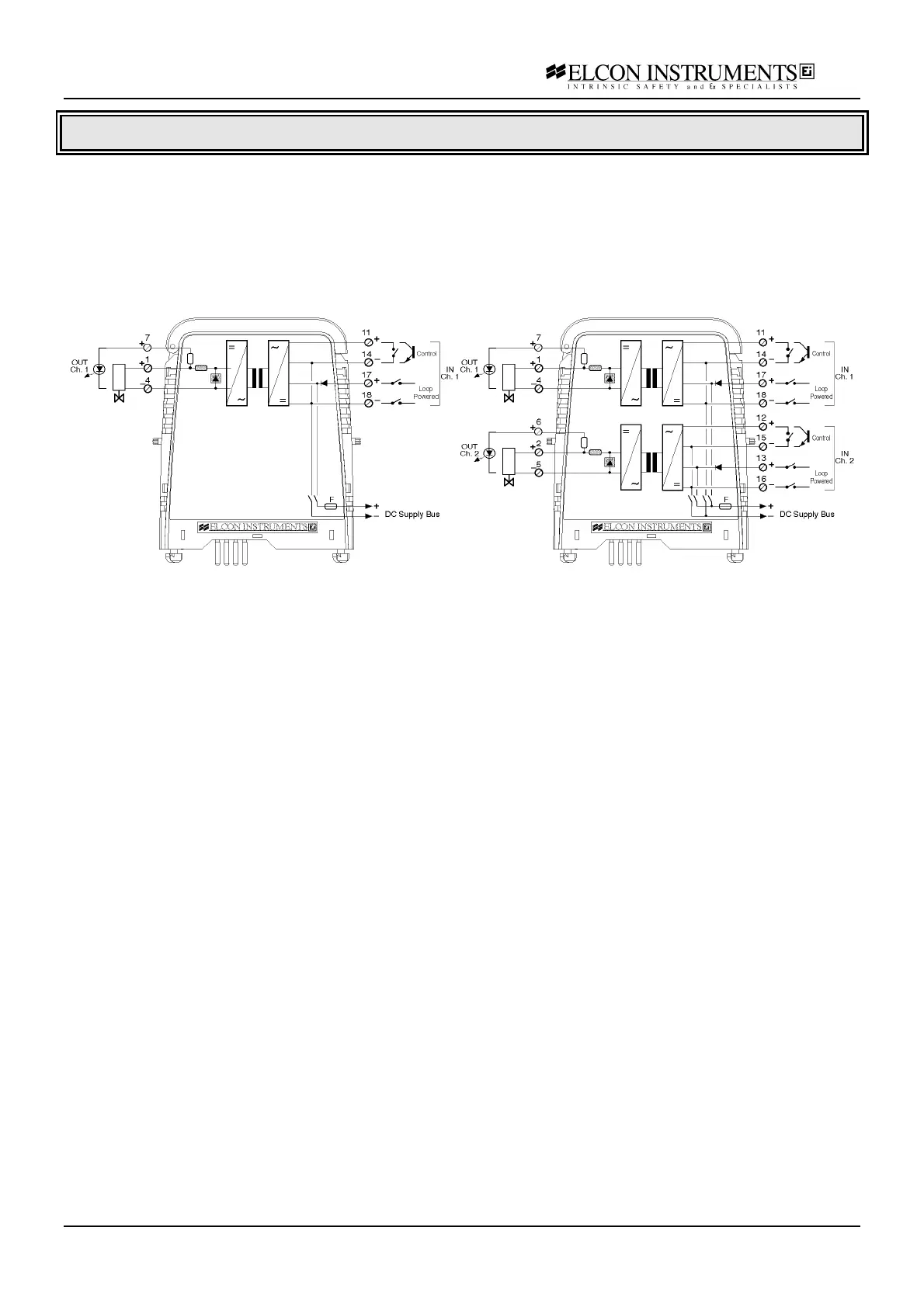
Model 2875 Model 2876
Application Guidelines
The unit can be used in Loop powered mode, with or without control signal, or in Bus powered mode with control.
When used in “loop powered” mode the unit receives as input in the safe area a 24 Vdc nominal power supply and
transfers it to the hazardous area where it is typically used to drive solenoid valves or audible alarms. When used
in “loop powered mode with control”, in addition to the power supply applied at the input terminal you must supply
a control input, such as a voltage free contact or open collector, to enable the output. As any other “loop powered”
isolator, the HiD 2875/HiD 2876 has a fail safe behaviour, i.e. if there is a loop supply fault, the isolator output is
de-activated. Also in this operating mode a field open circuit can be detected by monitoring safe area supply
current ( < 30 mA ). In “Bus powered” mode the power supply is given on termination board bus and so you need
to control the output only with the control input. The input/output relationship is fixed and is contact close or open
collector close/valve energised, which correspond the yellow status LED “lit”.
An hazardous area output is also available that can directly drive LED diodes without needing a series resistor.
NB. The two outputs cannot be used at the same time.
To verify the compatibility of the unit with the solenoid valve, you must have the minimum excitation current I
min
,
the maximum coil resistance R
coil
over the full operating temperature range and the voltage drop V
drop
across the
reverse polarity system if any. Calculate the working voltage by the formula V
work
= I
min
R
coil
+V
drop
and check that
voltage at the specified current value I
min
is below the output characteristic diagram.
The unit can be used with all Elcon standard termination board if programmed in “Bus powered mode”. If
programmed in “Loop powered mode”, with or without control, the /SACWT and /SACWCON termination board
cannot be used. The /HAKE termination board can not be used if connected to the low current output terminals
(LED output).