5-20
5.10 HiD 2071/2072
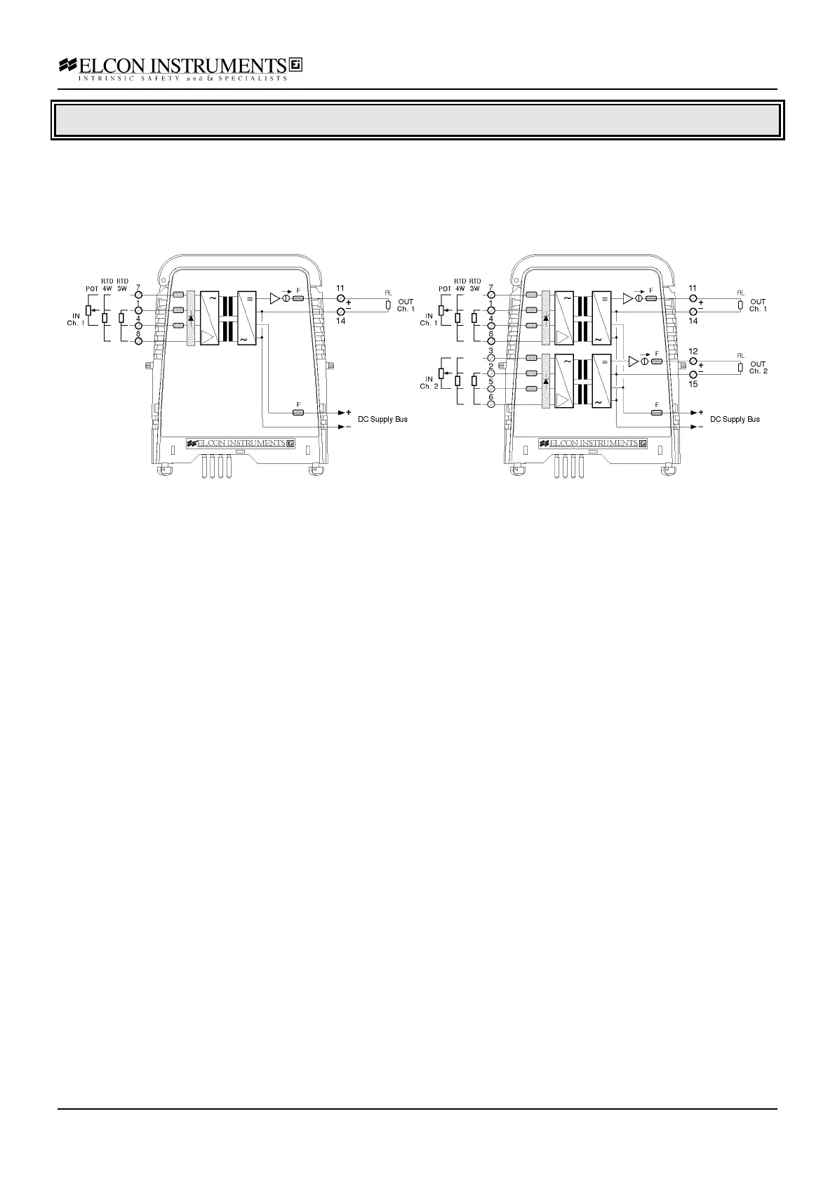
Functional description
Accepts input from Resistance Temperature Detectors (RTD) or Transmitting Potentiometers from a Hazardous
Area and converts them to an isolated analogue current signal in the Safe Area.
Input type, range and error handling parameters are configurable by switches and trimmers.
Outputs are isolated from input and referenced to the power supply common.
Model 2071 Model 2072
Application Guidelines
RTD Input
Input line resistance can range from 0 to 10 Ω for each of the three or four conductor without appreciably affecting
measuring accuracy (provided the three conductor resistances are balanced within at least ± 5%). Note that two
conductors should be connected together at the RTD sensor end for line resistance compensation.
You can also connect the RTD with two wires only by jumpering input terminals 4-8 (5-6 for channel 2) together. In
this case however, the line resistance and its associated change with cable temperature fluctuation will directly
add to the sensor resistance causing some measuring error. Note that a 0.385 Ω change of Sensor Resistance
corresponds to 1 °C of temperature change.
Potentiometer Input
The potentiometer resistance can range from 100 Ω to 100 KΩ, but its nominal value must be specified when
ordering to account for it in the calibration.
The unit can be used with all Elcon standard termination board except the /HAKE.