6-11
6.2.9 HiD 2822/2824
For these isolators, the input/output relationship is configurable. Two distinct check procedures are therefore
presented. For simplicity, the "fault detection disabled" mode is not covered by the procedure.
Input closed / relay output de-energised configuration:
a) for HiD 2822, set the configuration switches as: S1=ON, S2=ON, S3=ON, S4=ON
for HiD 2824, set the configuration switches as: S1=ON, S2=ON, S3=ON, S4=ON, S5=ON, S6=ON, S7=ON, S8=ON;
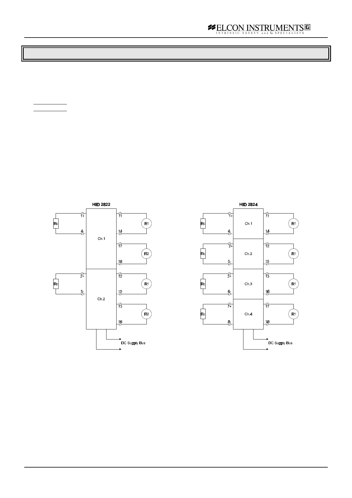
b) connect the power supply at the termination board supply terminals; connect the resistor box Rc at the input
terminals; connect the first multimeter R1 (resistance mode) at the output terminal; connect the second multimeter
R2 (resistance mode) at the second output terminal only for model HiD 2822; set the supply at 24 V and switch it
on; the green power LED must go on;
c) set the resistor box to 1 KΩ; both the yellow status and the red fault LED must be off; both multimeters (HiD
2822) or the tested channel multimeter (HiD 2824) must give a "open circuit" reading;
d) set the resistor box to 10 KΩ; the yellow status LED must be on and the red fault LED must be off; both
multimeters (HiD 2822) or the tested channel multimeter (HiD 2824) must give an "short circuit" reading;
e) set the resistor box to 0 Ω (input short-circuit); the yellow status LED must be off and the red fault LED must be
on; both multimeters (HiD 2822) or the tested channel multimeter (HiD 2824) must give an "open circuit" reading;
f) disconnect the resistor box (input open-circuit); the yellow status LED must be off and the red fault LED must be
on; both multimeters (HiD 2822) or the tested channel multimeter (HiD 2824) must give an "open circuit" reading;