6-23
6.2.15 HiD 2881
For this isolator, the Loop powered or Bus Powered function mode and the input type (contact or logic level) are
configurable. Three distinct check procedures are therefore presented.
Contact or Open Collector input type:
a) set the configuration switches as: S1=ON, S2=ON, S3=OFF, S4=ON, S5=ON, S6=ON;
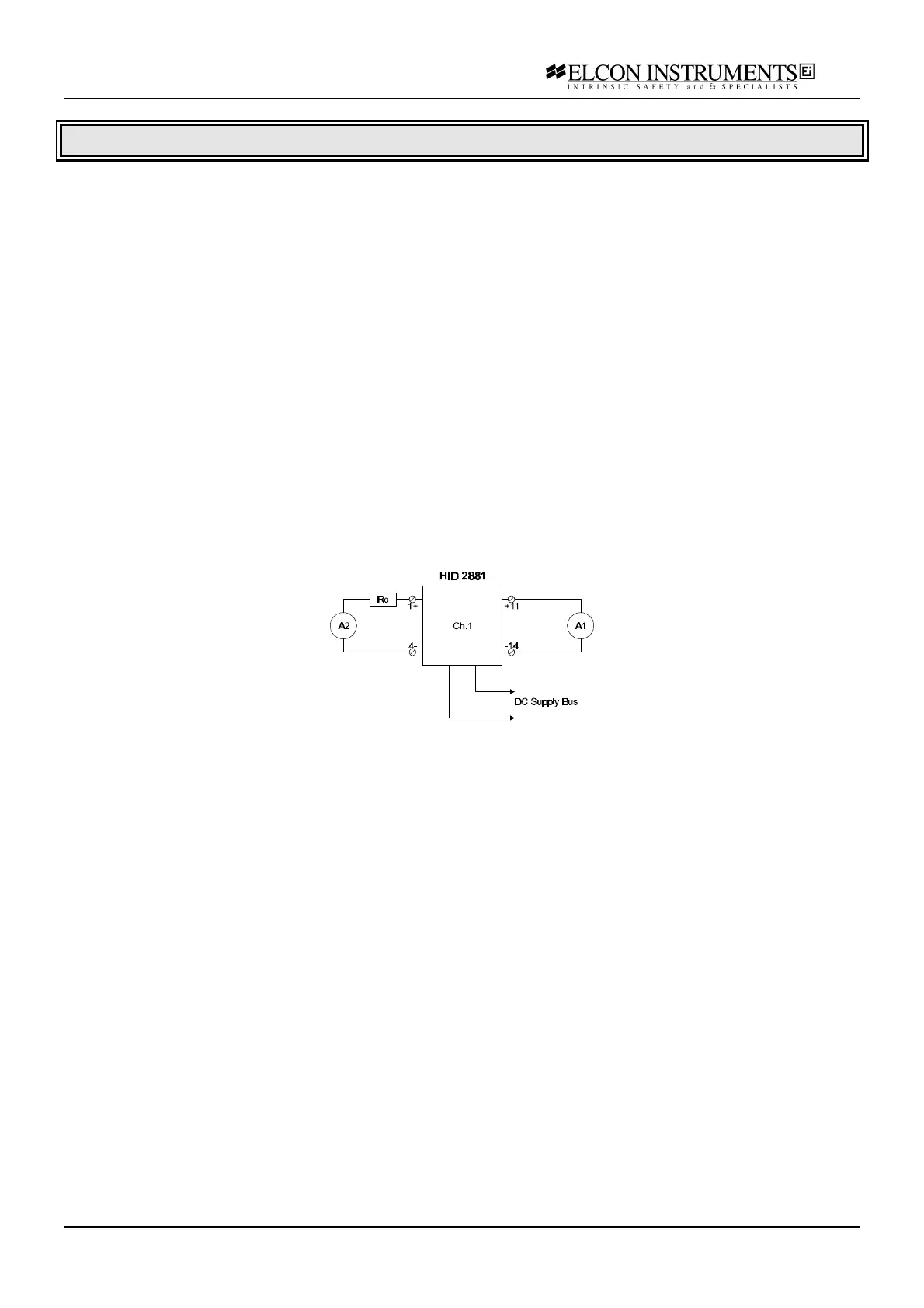
b) connect the power supply at the termination board supply terminals; connect the first multimeter A1 (current
mode) at the input terminals; connect the second multimeter A2 (current mode), in series with the resistor box Rc,
at the output terminals; set the supply at 24 V and switch it on; the green power LED must go on;
c) set the resistor box to 300 Ω; the output current must be within 46 and 54 mA; the yellow status LED must be on
and the red fault LED must be off;
d) set the resistor box to 0 Ω (output short-circuit); both the yellow status and the red fault LED must be on.
e) disconnect the resistor box (output open-circuit); both the yellow status and the red fault LED must be on.
f) re-connect the resistor box at the output terminals and set it to 300 Ω; the yellow status LED must be on and the
red fault LED must be off;
g) disconnect the input multimeter A1 (input open); the output current must be within 3 and 5 mA; both the yellow
status and the red fault LED must be off;
h) set the resistor box to 0 Ω (output short-circuit); the yellow status LED must be off and the red fault LED must
be on.
i) disconnect the resistor box (output open-circuit); the yellow status LED must be off and the red fault LED must
be on.