6-10
6.2.8 HiD 2037/2038
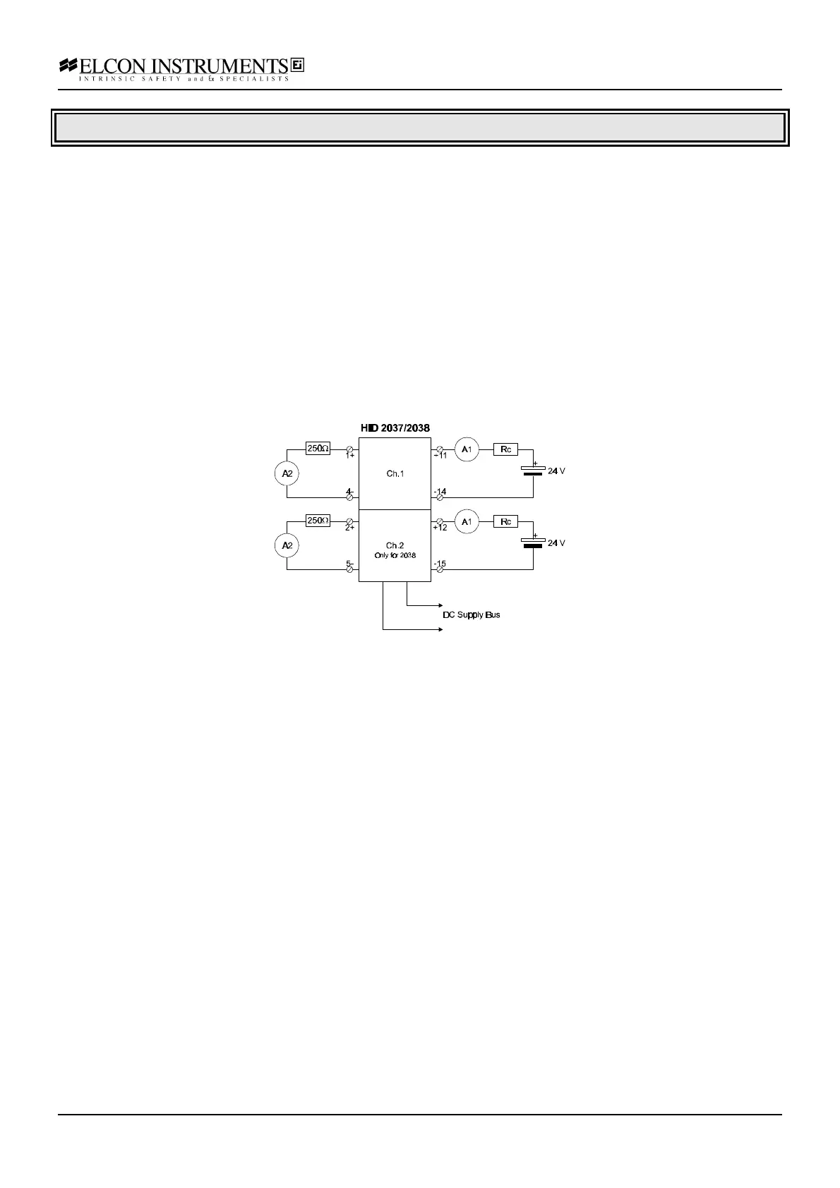
a) connect the power supply at the termination board supply terminals; feed the supply voltage, in series with the
first multimeter A1 (current mode) and with the resistor box Rc, at the input terminals; connect the second
multimeter A2 (current mode), in series with a 250 Ω resistor, at the output terminals; set the supply at 24 V and
switch it on; the green power LED must go on;
b) set the resistor box to 1.1 KΩ; the output current must be within 19.50 and 20.50 mA; the input current must be
the same, with an error lower than 20 µA; the red fault LED must be off.
c) set the resistor box to 5.6 KΩ; the output current must be within 3 and 5 mA; the input current must be the
same, with an error lower than 20 µA; the red fault LED must be off.
d) set the resistor box to 1.8 KΩ; the input current must be within 11 and 13 mA; the output current must be the
same, with an error lower than 20 µA; the red fault LED must be off.
e) connect the multimeter A2 at the output terminals without the external resistor (output short-circuit); the red fault
LED must be on;
f) disconnect the multimeter A2 at the output terminals (output open circuit); the input current must be lower than
1.2 mA; the red fault LED must be on;