5-41
5.17 HiD 2881
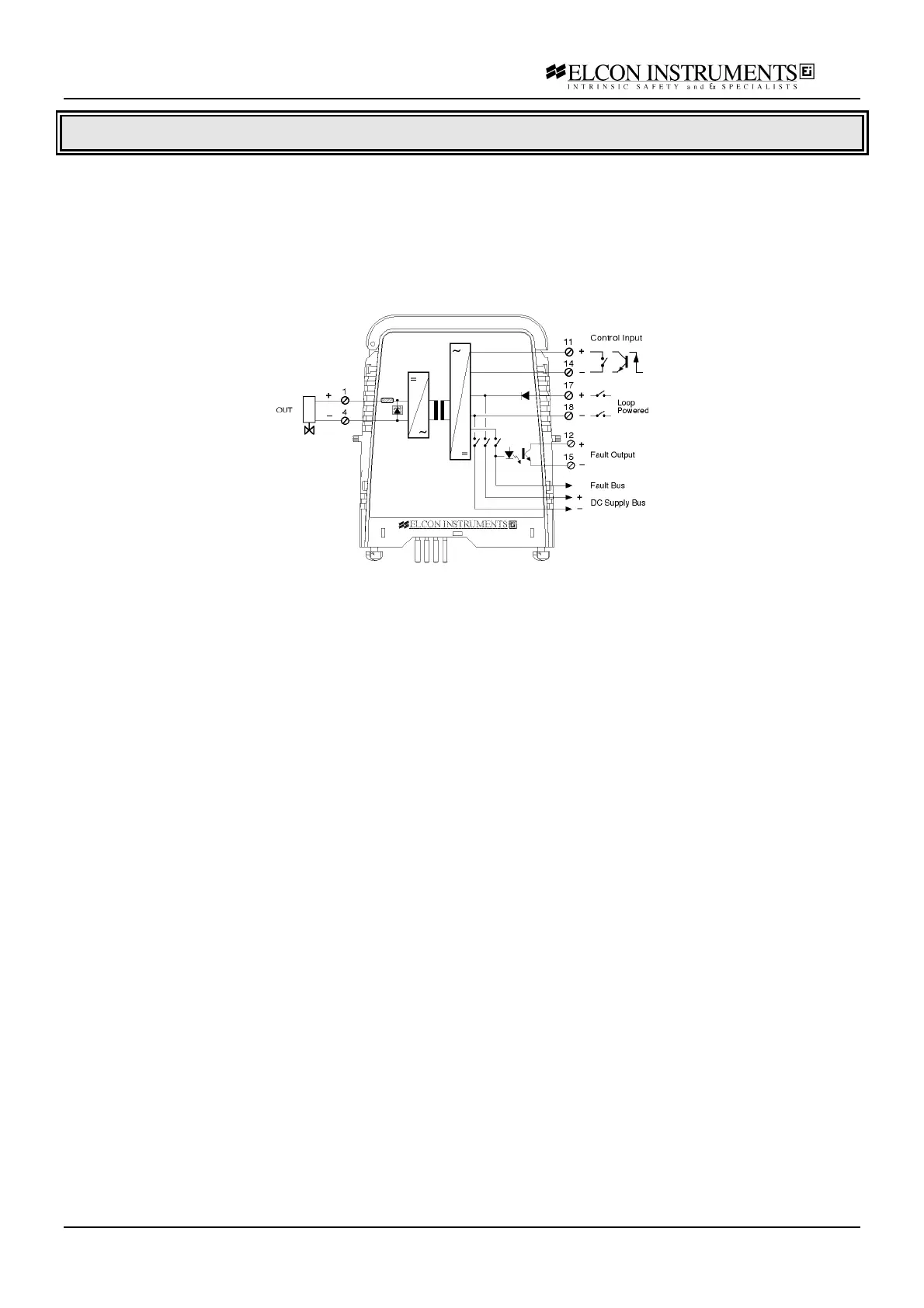
Functional description
Energises intrinsically safe solenoid valves in a Hazardous Area controlled by a Safe Area contact, transistor or
logic-level signal. A further programming mode allows the unit to be totally control loop powered ensuring high
integrity operation.
Line faults (open and short) can be detected and signalled by a LED, a fault bus output signal and an isolated
transistor which is energised in case of fault.
The high output power (60 mA at 13 V) is suitable for Gas Group IIB and IIA (Cenelec) or C-D (USA).
Model 2881
Application Guidelines
The unit function in Bus powered mode with control input that can be a voltage free contact, open collector or logic
level. The voltage free contact or open collector are referenced to supply line while the logic level is fully floating
with in respect to power supply. The unit transfers the input signal in the hazardous area where it is typically used
to drive solenoid valves or audible alarms. The input/output relationship is fixed and is contact close or open
collector close/valve energised or logic level high/valve energised, which correspond the yellow status LED “lit”.
To verify the compatibility of the unit with the solenoid valve, you must have the minimum excitation current I
min
,
the maximum coil resistance R
coil
over the full operating temperature range and the voltage drop V
drop
across the
reverse polarity system if any. Calculate the working voltage by the formula V
work
= I
min
R
coil
+V
drop
and check that
voltage at the specified current value I
min
is below the output characteristic diagram.
A separate fault output is signalled in case of field wiring shorted or opened. The segnalation is done by an fault
red LED “lit” and an optocoupled transistor closed when fault is present, and with common fault bus to de-activate
the optional fault monitor module on termination board. The line fault detection circuit is always active (with valve
energised or not energised) and when used with electronic valve an external paralleled resistor (typically 4.7 KΩ)
must be applied to the output terminals, close to valve, to prevent abnormal fault segnalation. Contact Elcon for
more details. To prevent fault segnalation on spare module is necessary to connect a 4.7 KΩ ½ W resistor across
the valve output terminals 1-4.
The unit can be used with all Elcon standard termination board if programmed in “Bus powered mode”. If
programmed in “Loop powered mode”, with or without control, the /SACWT and /SACWCON termination board
cannot be used.