5-26
5.12 HiD 2842/2844
Functional description
Repeats the status of a voltage free contact or IS proximity sensor in a Hazardous Area to a solid state output(s) in
a Safe Area.
The line fault detection feature (primarily used with proximity sensor) de-energises the output signal, gives an LED
indication and is signalled by a separate fault output.
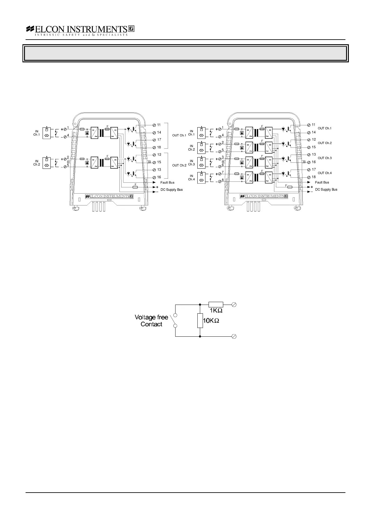
Model 2842 Model 2844
Application Guidelines
The unit supply the required power to field contact/sensor; no additional power supply is required. A “open” contact
status is equivalent to the status of an object “near” to the proximity sensor. When the yellow status LED is “lit”,
the output transistors are closed. To get the desired input/output relationship configure the switch properly in
according to the configuration table. When a fault condition is present, and the LFD is enabled, the transistors are
always in the opened status and the fault red segnalation LED is “lit”. On the dual channel unit, the two output
transistors per channel are always driven in parallel.
The unit is designed to operate in high frequency switching application due to the transistor output.
To get a fault-detection capability when the input is a voltage free contact ( i.e. not a proximitor ), use the following
circuit located at the end of the line, near the field contact:
To prevent fault segnalation on spare channel/module is necessary to connect a 10 KΩ ½ W resistor across the
input terminals 1-4, 2-5, 3-6 and/or 7-8.
The unit can be used with /HAT, /SAT, /SACON termination board for all channel. The /HAKE termination board
can be used only for model HiD 2842. The /SACWT, /SACWCON can be used only for model HiD 2842 using
single output channel (not duplicated).