5-7
5.4 HiD 2029SK/2030SK
Functional description
Provides a fully floating supply to power a two or three wire transmitter in a Hazardous Area, repeating the current
in sink mode to simulate a two wire transmitter load in Safe Area. Bi-directional communication is provided for
smart transmitters which use current modulation to transmit data and voltage modulation to receive data.
Outputs are isolated from the inputs, the power supply and each other.
A separate fault output is signalled if the input signal is outside the range 0.2-24 mA
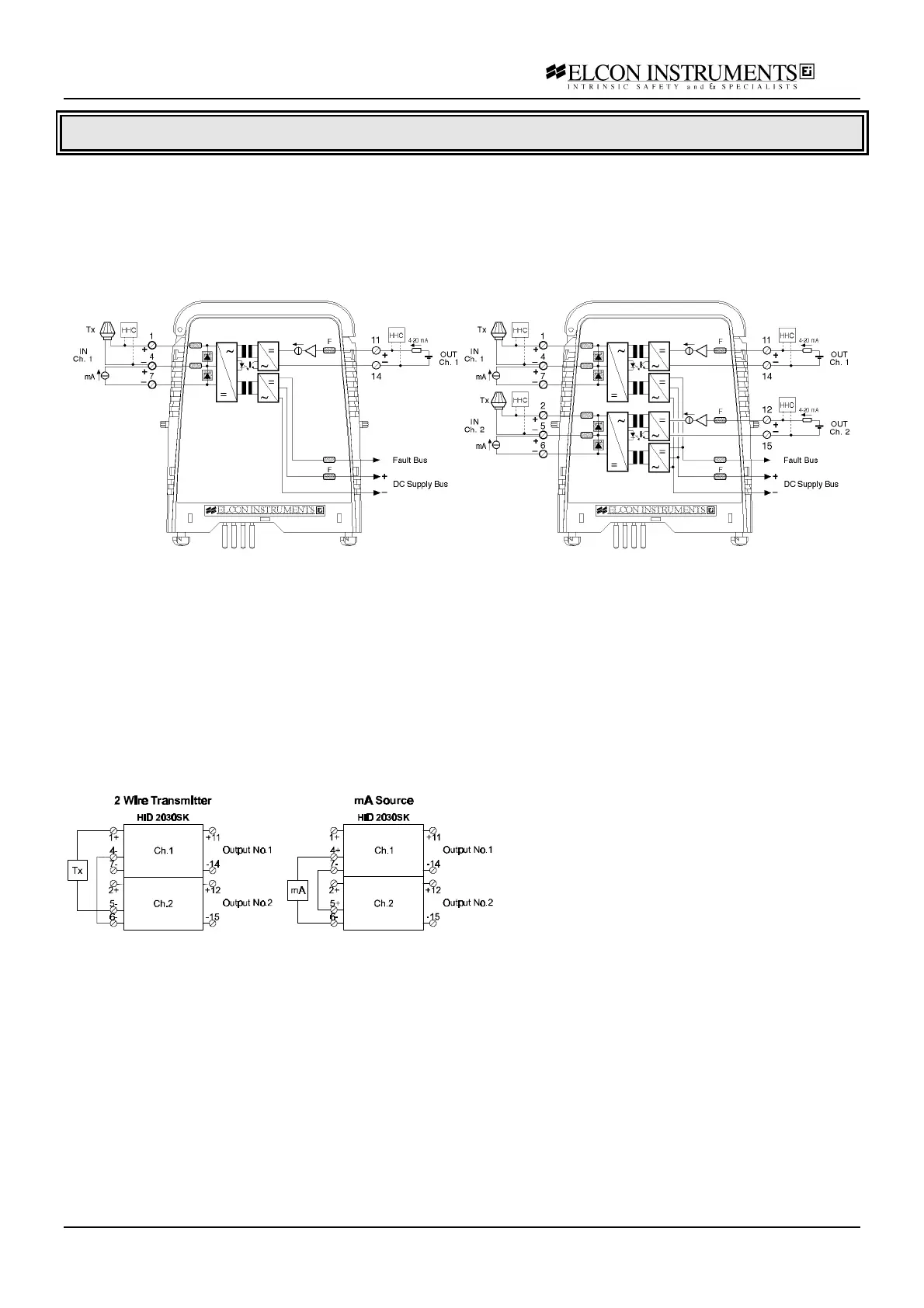
Model 2029SK Model 2030SK
Application Guidelines
The barrier outputs are fully isolated from supply and must be used when ground loop should be avoided. The
outputs are sink mode so an external power supply must be connected to the output terminal. Note that the barrier
requires a minimum voltage of 7 V to work properly. If in the loop there are several series equipment be care that
the minimum voltage applied conform to specification. The specified operating range is 4-20 mA, but the unit can
operate near 0 mA with reduced accuracy. Please contact Elcon for more details. At the field side, the equivalent
circuit (before current limitation) is around 21 V / 300 Ω
A separately power current source device can be connected on passive input terminals, which in fact act as a sink
input. When considering three wire transmitter always check required supply voltage and current operating range.
The unit HiD 2030SK is suitable to perform a single input-dual outputs connection with an external cross wire as
shown in figure:
An Hand Held Configurator (HHC) for smart transmitters configuration can be connected either at the SA and at
HA side (in this case you need an IS certified HHC). When in SA, a minimum load of 250 Ω must be present on
the current loop and the HHC must be connected across the output terminals of the unit. When the DCS/PLC has
a low current sense resistor, you need to insert an external series resistor to get proper communication.
A separate fault output is signalled if the input signal is outside the range 0.2-24 mA. The segnalation is done by
an LED (ON when fault is present, OFF in normal condition) and with common fault bus to de-activate the optional
fault monitor module on termination board. Fault output is not present when the input signal is between 1.0 mA
and 23.5 mA range. To prevent fault segnalation on spare channel/module is necessary to connect a 10 KΩ ½ W
resistor across the transmitter input terminals 1-4 and/or 2-5.
The unit can be used with all Elcon standard termination board when connected to transmitter. When used on
passive input terminal the unit can not be used with /HAKE termination board.
Note that some restrictions may apply:
• bi-directional communication for smart
transmitter is provided only on output
channel No. 1
• the minimum supply voltage available for
transmitter is 14.7 V @ 20 mA
• the allowable safety parameters must be
changed in
U
0
=27.45 V, I
0
=93 mA and P
0
=640 mW