5-8
Connection Information
Please refer to the electrical schematics above and to the electrical connection section 4.7.
For more details please refer to the Termination Board Instruction Manual.
Model HiD 2029SK:
Screw terminal number Used for
11 Safe area output +
14 Safe area output -
19 Safe area Shield
12, 13, 15, 16, 17, 18 not used
1 Hazardous area 2 wire (smart) Tx +
4 Hazardous area 2 wire (smart) Tx -, mA +
7 Hazardous area mA -
9 Hazardous area Shield
2, 3, 5, 6, 8 not used
Model HiD 2030SK:
Screw terminal number Used for
11 Safe area output +, Ch. 1
14 Safe area output -, Ch. 1
12 Safe area output +, Ch. 2
15 Safe area output -, Ch. 2
19 Safe area Shield
13, 16, 17, 18 not used
1 Hazardous area 2 wire (smart) Tx +, Ch. 1
4 Hazardous area 2 wire (smart) Tx -, mA +, Ch. 1
7 Hazardous area mA -, Ch. 1
2 Hazardous area 2 wire (smart) Tx +, Ch. 2
5 Hazardous area 2 wire (smart) Tx -, mA +, Ch. 2
6 Hazardous area mA -, Ch. 2
9 Hazardous area Shield
3, 8 not used
Configuration options
No user configuration available for this device.
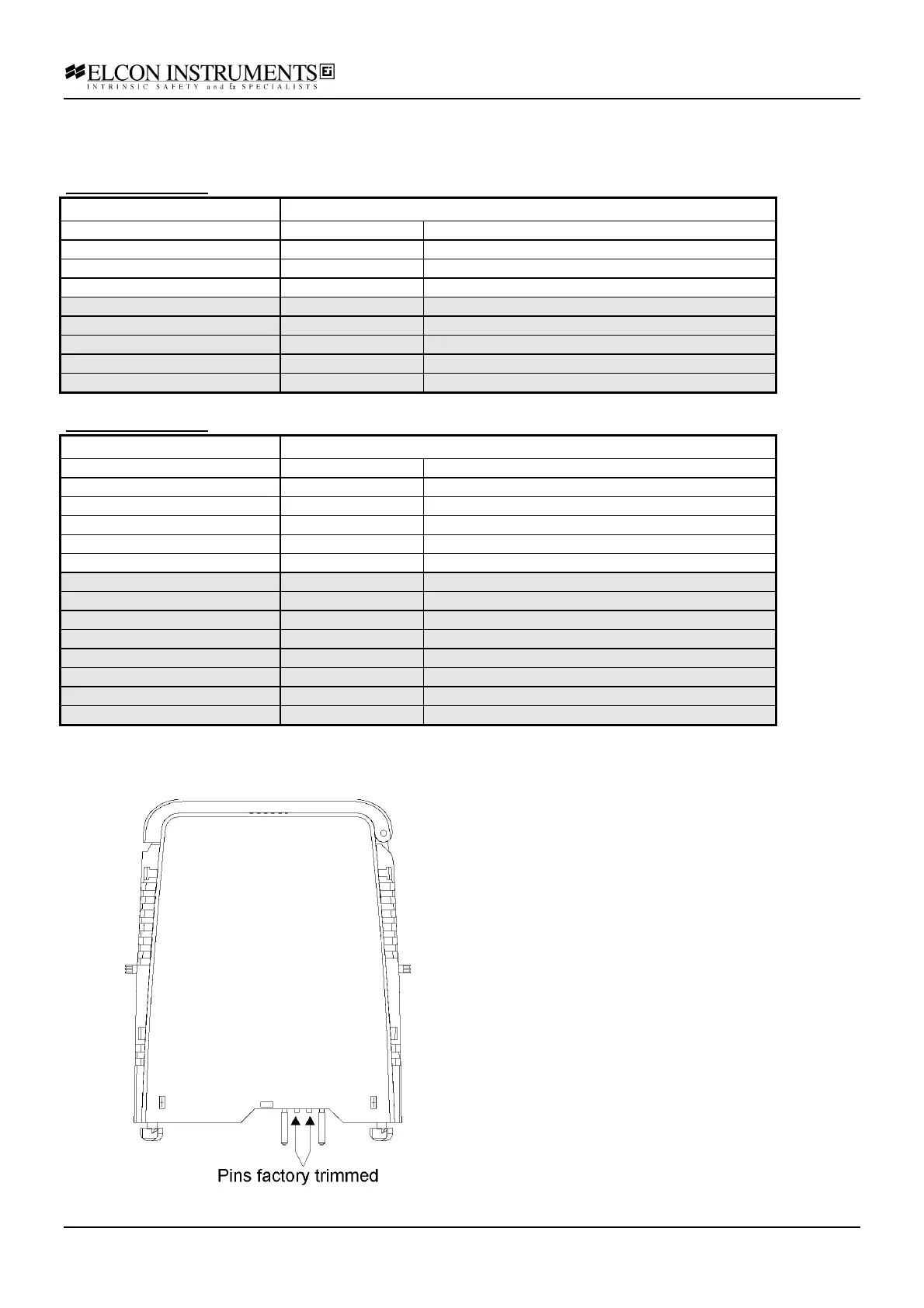
The prongs for this model are trimmed to polarise it
according to it’s safety parameter. Please do not
change. See chapter 4.5 for more details.