5-6
Connection Information
Please refer to the electrical schematics above and to the electrical connection section 4.7.
For more details please refer to the Termination Board Instruction Manual.
Model HiD 2029:
Screw terminal number Used for
11 Safe area output +
14 Safe area output -
19 Safe area Shield
12, 13, 15, 16, 17, 18 not used
1 Hazardous area 2 wire (smart) Tx +
4 Hazardous area 2 wire (smart) Tx -, mA +
7 Hazardous area mA -
9 Hazardous area Shield
2, 3, 5, 6, 8 not used
Model HiD 2030:
Screw terminal number Used for
11 Safe area output +, Ch. 1
14 Safe area output -, Ch. 1
12 Safe area output +, Ch. 2
15 Safe area output -, Ch. 2
19 Safe area Shield
13, 16, 17, 18 not used
1 Hazardous area 2 wire (smart) Tx +, Ch. 1
4 Hazardous area 2 wire (smart) Tx -, mA +, Ch. 1
7 Hazardous area mA -, Ch. 1
2 Hazardous area 2 wire (smart) Tx +, Ch. 2
5 Hazardous area 2 wire (smart) Tx -, mA +, Ch. 2
6 Hazardous area mA -, Ch. 2
9 Hazardous area Shield
3, 8 not used
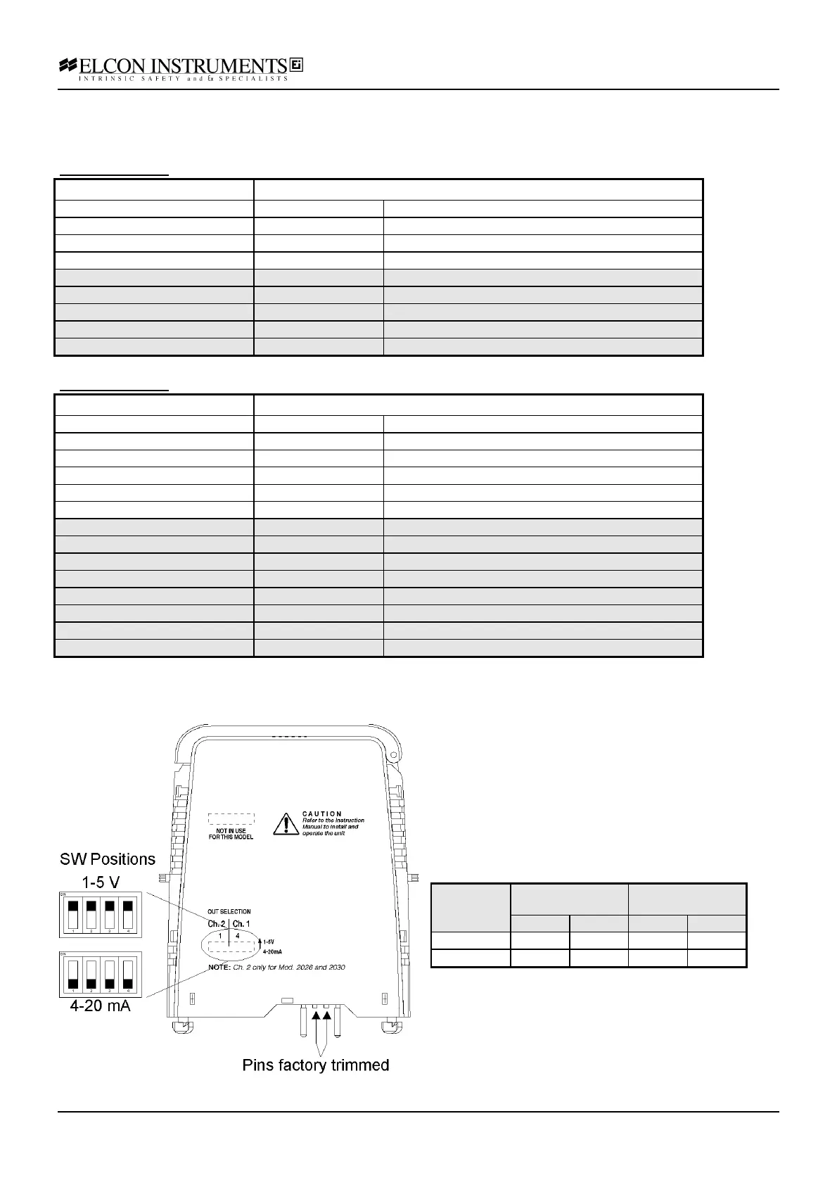
Configuration options
The outputs can be configured as:
• Current output 4-20 mA
• Voltage output 1-5 V
The configuration is performed in the following way:
• remove the module from termination board
pulling-up the tab on each side of the module
• set the dip-switches with a small screwdriver or
similar, according to the figure and to the table
Output Ch.1 Ch.2
(Only for HiD 2030)
SW4 SW3 SW2 SW1
4-20 mA OFF OFF OFF OFF
1-5 V ON ON ON ON
The prongs for this model are trimmed to polarise it
according to it’s safety parameter. Please do not
change. See chapter 4.5 for more details.