5-42
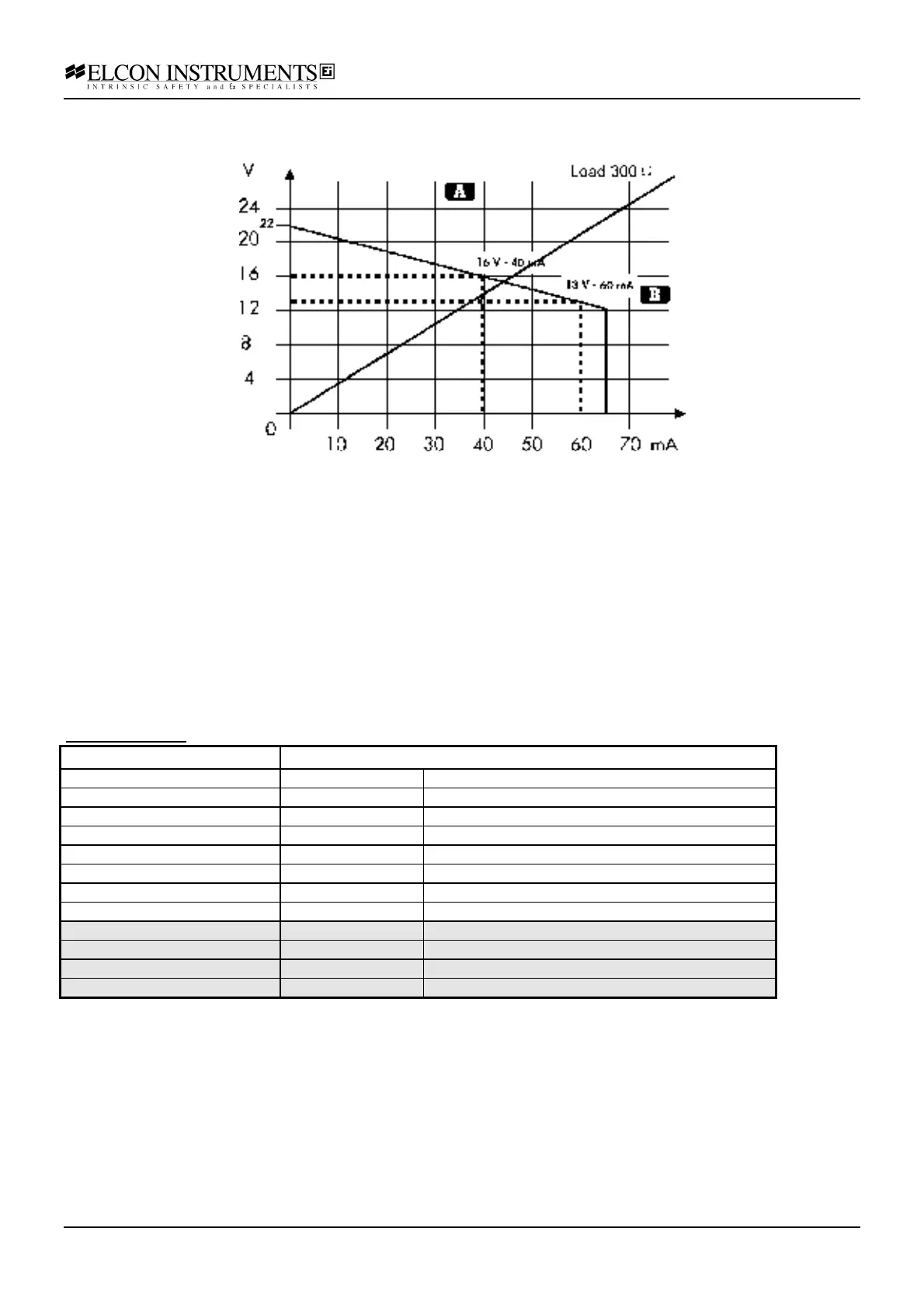
The voltage-current relationship is shown in the picture below. Please note that the output voltage is not stabilised
but it is load dependent.
The HiD 2881 module can, in some operating conditions, transfer to the output an amount of power that is relevant
when compared with the reduced case size. It is therefore required to adopt proper mounting techniques such as
to avoid a too high operating temperature, which can have an impact on reliability and expected life time. With
reference to the above figure, and in function of the output load, the operating area is to be identified:
• with a normal load ( A zone, Rload>300 Ω ), be careful to keep free from any obstruction the case venting
slits.
• with a high load ( B zone, Rload<300 Ω ), it must be necessary to adopt a proper forced ventilation within
the cabinet or plug the modules on horizontally positioned termination board.
Connection Information
Please refer to the electrical schematics above and to the electrical connection section 4.7.
For more details please refer to the Termination Board Instruction Manual.
Model HiD 2881:
Screw terminal number Used for
11 Safe area control input +
14 Safe area control input -
12 Safe area fault output +
15 Safe area fault output -
17 Safe area loop powered input +
18 Safe area loop powered input -
19 Safe area Shield
13, 16 not used
1 Hazardous area output +
4 Hazardous area output -
9 Hazardous area Shield
2, 3, 5, 6, 7, 8 not used