4-4
Horizontal mounting:
This type of installation is similar to the “reference condition”, so the temperature just beneath the units is to be
estimated. With a reasonable vertical spacing (around 20 cm / 8 inches) or with some ventilation, the temperature
beneath the units is likely to be close to the average temperature within the cabinet. With reduced spacing and no
ventilation, a safety margin of 10 °C is recommended, unless you can afford to measure the real temperature
beneath the units.
Vertical mounting:
Because this is a less favourable condition for power dissipation, it is recommended that forced ventilation is used
in such a way that a steady air flow is provided on one side of the vertical columns of units. In this case, the
temperature of the air flow –which is the applicable operating temperature- is close to the average temperature
within the cabinet.
If forced ventilation is not possible, it is recommended that the power dissipation of each unit is estimated within
the proposed model mix layout. In most situations, it is acceptable to perform an average power dissipation
assessment, with 70% of digital channels in the energised state and 70% of the analogue channels operating at
full scale.
The following table can be used to assess the temperature situation of a given model when in a vertical mounting
situation. The 70% power dissipation figures are summarised in the following section.
70% Power Dissipation Applicable operating temperature
0-1 W : air temperature immediately below the row (no derating)
1-2 W : air temperature immediately below the row plus 20 °C (derating)
2-3 W : forced ventilation mandatory
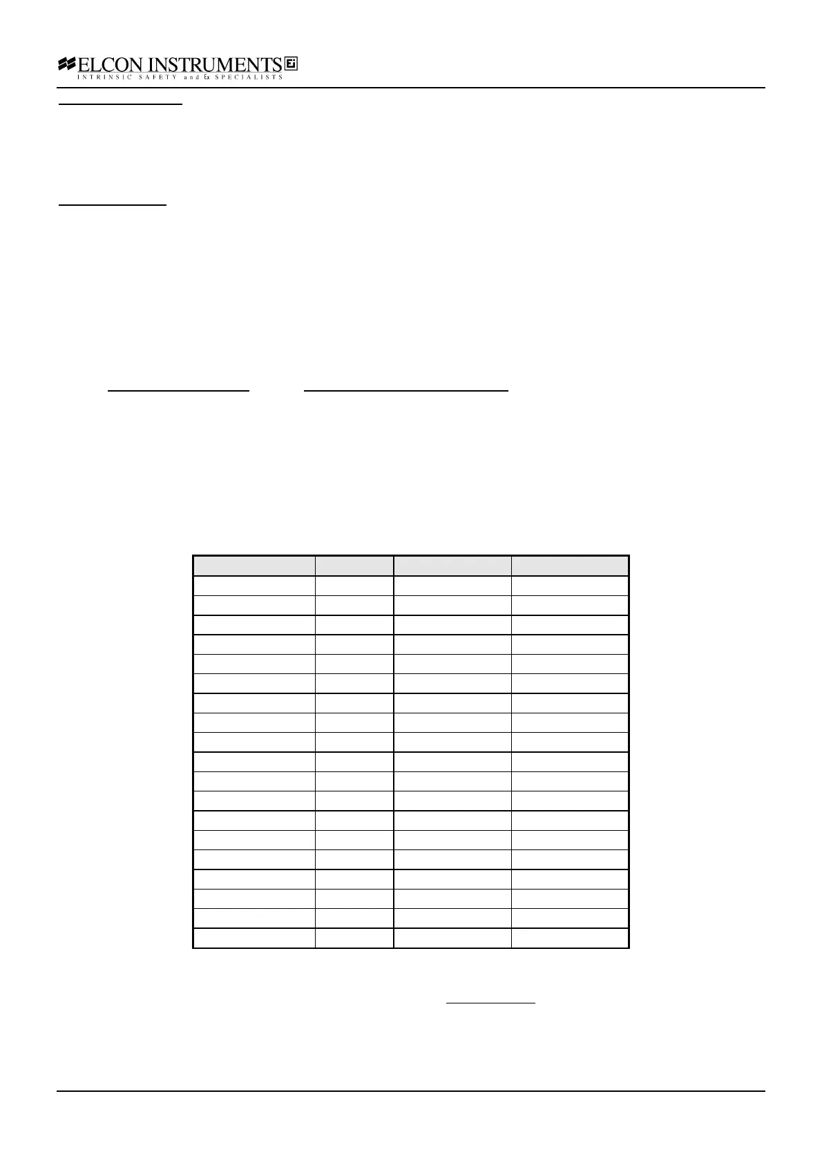
Power Dissipation Summary
The power dissipation specified for each model is shown in the table following (dividing by 2, you can get the
single channel dissipation). The specified figures are at 24V, 20 mA (or energised status) and nominal loads. The
final column provides the 70% power dissipation figures.
Isolator Channels Nominal power
70% power
2026SK 2 2.6 W 1.8 W
2872 2 2.4 W 1.7 W
2876 2 2.4 W 1.7 W
2874 2 2.2 W 1.5 W
2030SK 2 2.1 W 1.5 W
2030 2 2.1 W 1.5 W
2878 2 2.0 W 1.4 W
2038 2 1.7 W 1.2 W
2026 2 1.6 W 1.1 W
2032 2 1.5 W 1.0 W
2822 2 0.7 W 0.5 W
2824 4 1.4 W 1.0 W
2842 2 0.7 W 0.5 W
2844 4 1.4 W 1.0 W
2036 2 1.4 W 1.0 W
2881 1 1.3 W 0.9 W
2062 2 1.2 W 0.8 W
2072 2 1.2 W 0.8 W
2034 2 0.3 W 0.2 W
Temperature Accuracy
The accuracy provided in the standard Elcon specifications for analogue units is at an operating temperature of
23 °C, after a 15 minutes warm-up and in the “reference conditions” as described at the beginning of section 4.9.
When a different operating temperature is applicable -according to the discussion in the previous sections- you
should take into account the thermal drift. The specified drift (generally 0.01% /°C), is a worst case value, typical
behaviour is usually better.
As for digital units (i.e. ON/OFF devices) no thermal drift is usually specified.