5-22
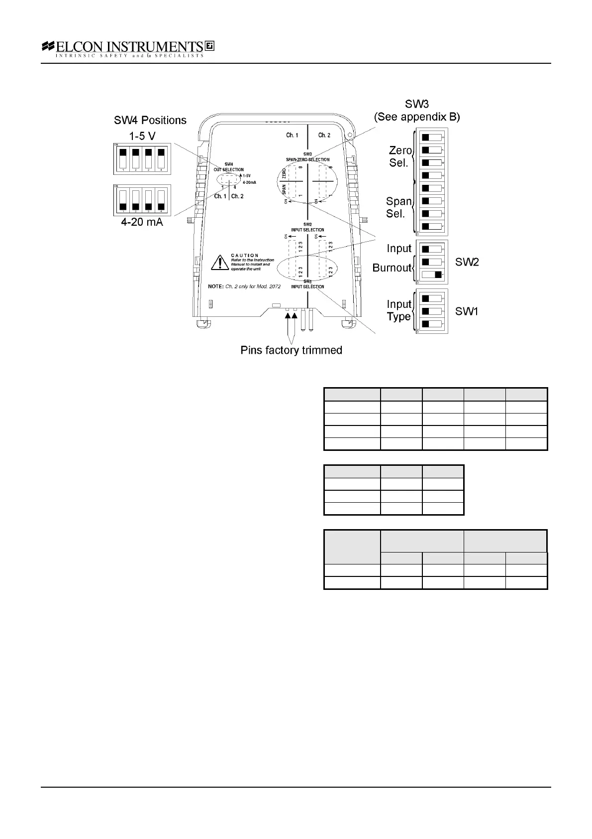
Configuration options
The inputs can be configured as:
• RTD ( 2, 3 or 4 wire ) or POT
• Input Zero and Span Value
• Burnout segnalation UP or DOWN (only for RTD 2, 3
wire)
The outputs can be configured as:
• Current output 4-20 mA
• Voltage output 1-5 V
The configuration is performed in the following way:
• remove the module from termination board pulling-up
the tab on each side of the module
• set the dip-switches according to the figure and to the
tables
The prongs for this model are trimmed to polarise it
according to it’s safety parameter. Please do not change.
See chapter 4.5 for more details.
Input SW1-1 SW1-2 SW1-3 SW2-3
RTD 2 W ON ON ON ON
RTD 3 W ON ON ON ON
RTD 4 W ON OFF OFF ON
POT OFF OFF OFF OFF
Burnout SW2-1 SW2-2
UP ON OFF
DOWN OFF ON
POT Input OFF OFF
Output Ch.1 Ch.2
(Only for HiD 2072)
SW4-1 SW4-2 SW4-3 SW4-4
4-20 mA OFF OFF OFF OFF
1-5 V ON ON ON ON
Note: for input range setting refer to appendix
B for Zero and Span Tables. Also refer to
appendix B for calibrating instructions.