5-37
Connection Information
Please refer to the electrical schematics above and to the electrical connection section 4.7.
For more details please refer to the Termination Board Instruction Manual.
Model HiD 2875:
Screw terminal number Used for
11 Safe area control input +
14 Safe area control input -
17 Safe area loop powered input +
18 Safe area loop powered input -
19 Safe area Shield
12, 13, 15, 16 not used
7 Hazardous area low current output +
1 Hazardous area high current output +
4 Hazardous area current output -
9 Hazardous area Shield
2, 3, 5, 6, 8 not used
Model HiD 2876:
Screw terminal number Used for
11 Safe area control input +, Ch. 1
14 Safe area control input -, Ch. 1
17 Safe area loop powered input +, Ch. 1
18 Safe area loop powered input -, Ch. 1
12 Safe area control input +, Ch. 2
15 Safe area control input -, Ch. 2
13 Safe area loop powered input +, Ch. 2
16 Safe area loop powered input -, Ch. 2
19 Safe area Shield
7 Hazardous area low current output +, Ch. 1
1 Hazardous area high current output +, Ch. 1
4 Hazardous area current output -, Ch. 1
6 Hazardous area low current output +, Ch. 2
2 Hazardous area high current output +, Ch. 2
5 Hazardous area current output -, Ch. 2
9 Hazardous area Shield
3, 8 not used
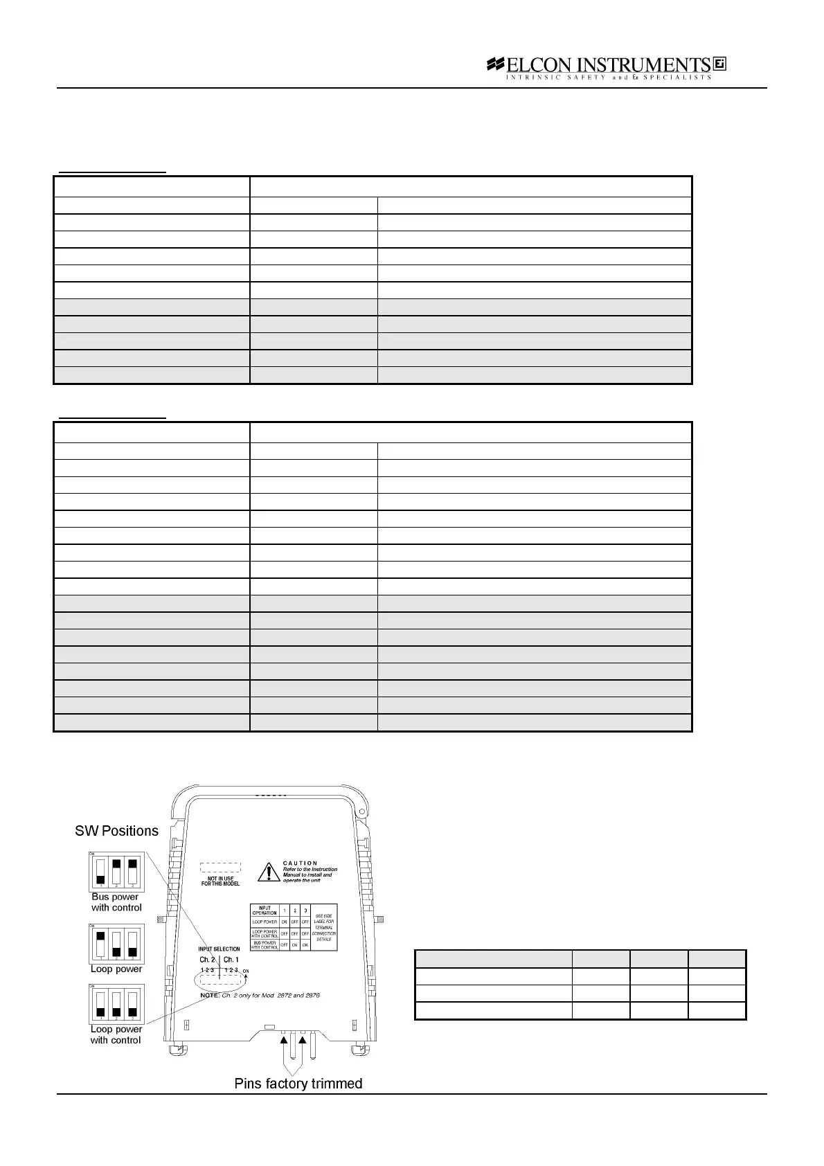
Configuration options
The inputs control type can be configured as:
• loop powered with control
• loop powered without control
• bus powered with control
The configuration is performed in the following way:
• remove the module from termination board
pulling-up the tab on each side of the module
• set the dip-switches according to the figure and
to the table
Input SW1 SW2 SW3
Loop power with control OFF OFF OFF
Loop power ON OFF OFF
Bus power with control OFF ON ON
The prongs for this model are trimmed to polarise it
according to it’s safety parameter. Please do not
change. See chapter 4.5 for more details.