6-14
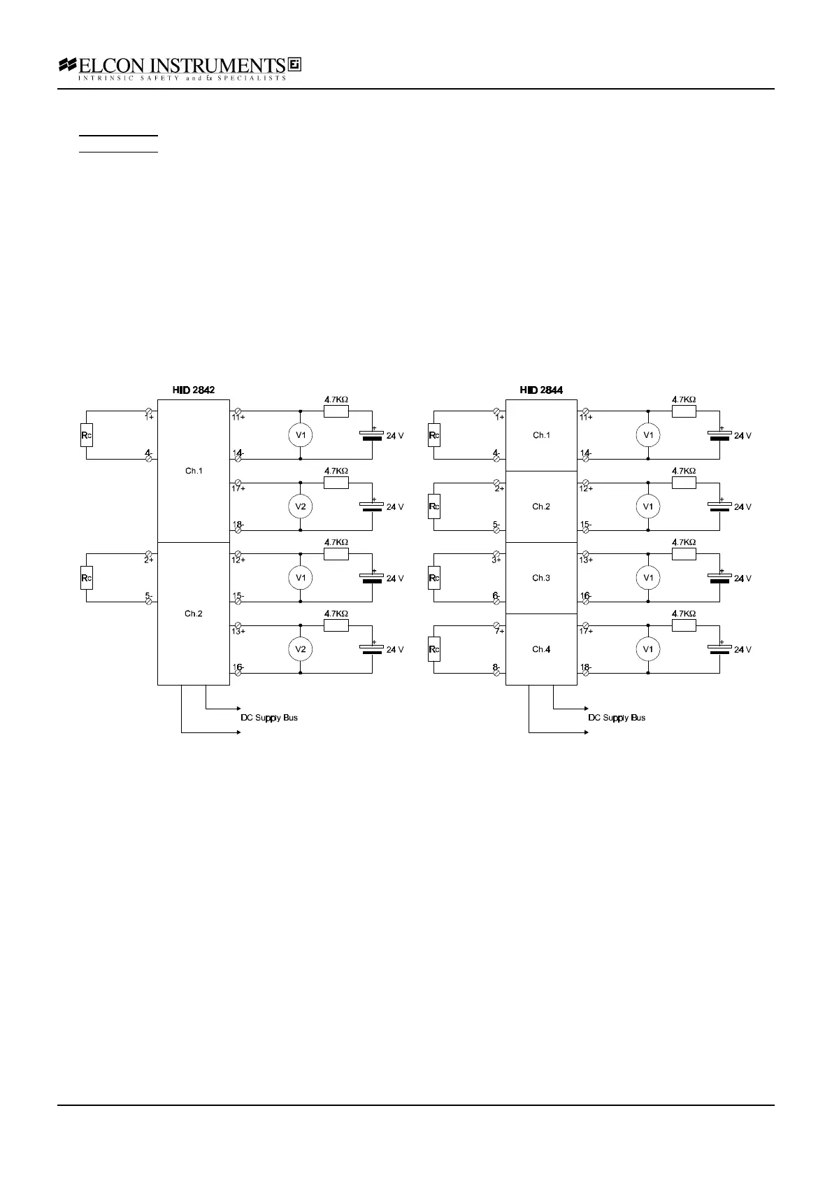
Input closed / transistor output closed configuration:
a) for HiD 2842, set the configuration switches as: S1=OFF, S2=ON, S3=OFF, S4=ON
for HiD 2844, set the configuration switches as: S1=OFF, S2=ON, S3=OFF, S4=ON, S5=OFF, S6=ON, S7=OFF, S8=ON;
b) connect the power supply at the termination board supply terminals; connect the resistor box Rc at the input
terminals; feed the supply voltage, in series with a 4.7 KΩ resistance at the output terminal ( 2 transistor output
only for model HiD 2842 ); connect the first multimeter V1 (voltage mode) at the output terminal in parallel with the
output transistor; connect the second multimeter V2 (voltage mode) at the second output terminal only for model
HiD 2842; set the supply at 24 V and switch it on; the green power LED must go on;
c) set the resistor box to 1 KΩ; the yellow status LED must be on and the red fault LED must be off; both
multimeters (HiD 2842) or the tested channel multimeter (HiD 2844) must give a "< 1 V" reading;
d) set the resistor box to 10 KΩ; both the yellow status and the red fault LED must be off; both multimeters (HiD
2842) or the tested channel multimeter (HiD 2844) must give a "24 V" reading;
e) set the resistor box to 0 Ω (input short-circuit); the yellow status LED must be off and the red fault LED must be
on; both multimeters (HiD 2842) or the tested channel multimeter (HiD 2844) must give an "24 V" reading;
f) disconnect the resistor box (input open-circuit); the yellow status LED must be off and the red fault LED must be
on; both multimeters (HiD 2842) or the tested channel multimeter (HiD 2844) must give an "24 V" reading;