6-16
Bus powered mode:
a) for HiD 2871, set the configuration switches as: S1=OFF, S2=ON, S3=ON Ch.1
for HiD 2872, set the configuration switches as: S1=OFF, S2=ON, S3=ON Ch.1, S1=OFF, S2=ON, S3=ON Ch.2;
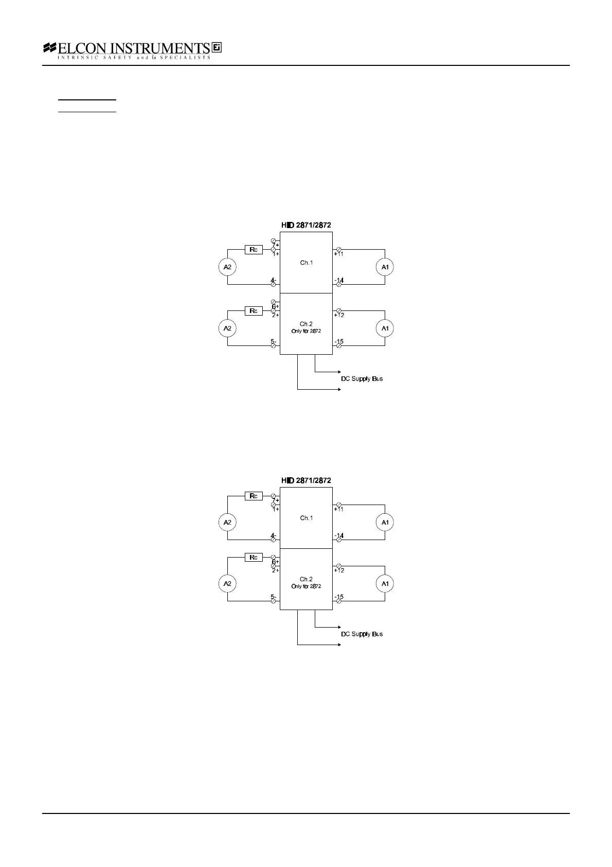
b) connect the power supply at the termination board supply terminals; connect the first multimeter A1 (current
mode) at the “Control” input terminals, connect the second multimeter A2 (current mode), in series with the resistor
box Rc, at the "solenoid valve" output terminals; set the supply at 24 V and switch it on; the green power LED
must go on;
c) set the resistor box to 300 Ω; the output current must be within 40 and 42 mA; the yellow status LED must be
on;
d) disconnect the input multimeter A1 (input open-circuit); the output current must be 0; the yellow status LED
must be off;
e) re-connect the input multimeter A1 and connect the multimeter A2 (current mode), in series with the resistor box
Rc, at the "LED" output terminals;
f) set the resistor box to 0 Ω; the output current must be within 18 and 24 mA; the yellow status LED must be on;
g) disconnect the input multimeter A1 (input open-circuit); the output current must be 0; the yellow status LED
must be off;