1 Introduction
iConnect Installation Manual
4
1.4. Hardware Layout
The aim of this section is to acquaint you with the various circuit boards that make up the system. Apart from the Main
Board, each peripheral module is available as an optional extra designed for installation inside the plastic housing.
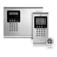
Figure 1-2: System Layout
1. Main Board
2. Communication module (GPRS + GSM + PSTN, or Ethernet + PSTN, or PSTN-only).
3. Home Automation module (optional)
4. Backup battery pack.
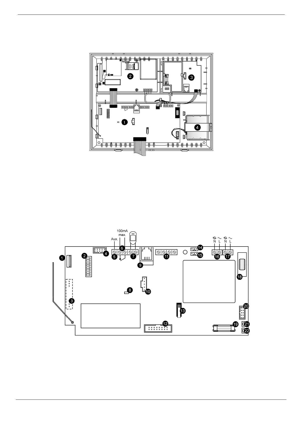
1.4.1. The Main Board
The Main Board is the brain of the system and connects to various peripheral modules using a number of interface
connectors. Additionally, the Main Board includes a programmable output, and a hardwire zone input.
Figure 1-3: Main Board
1. USB port (not used)
2. DIP-switch for flash programming
3. Connector for on-board transmitter
4. Flat-cable interface connector to
communication module
5. Auxiliary power output (for Control Systems
operated by AC: 10-15Vdc, for Control
11. System bus terminal block (hardwire LCD
keypad, Wired Zone Module)
12. Flat-cable interface connector to hardwire LCD
keypad, built-in speaker, microphone and siren
13. Front tamper switch
14. Not in use
15. Interface connector to Home Automation module