3 Basic System Operation
iConnect Installation Manual
16
3. Basic System Operation
iConnect Control System is available in two front panel configurations: LED and LCD. Below you will find description
of the LCD front panel layout. For LED Top Cover layout see p. 19, 3.5 Front Panel Layout (LED Top Cover).
3.1. Front Panel Layout (LCD Top Cover)
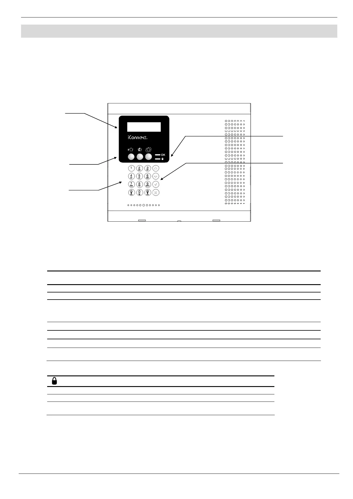
The LCD front panel provides a detailed interface for operating and programming the system. The following diagram
will familiarize you with the various elements on the front panel.
Figure 3-1: Front Panel
3.2. Front Panel System Status LEDs (LCD Top Cover)
The two LEDs, OK and Arm Status, provide essential information on the status of the system.
OK LED Status
Meaning
Off Both AC and Battery power are disconnected.
Green On System Power Status is OK and there is System Trouble.
Green Flashing
Open Zone. Check that the windows and doors are closed and no movement is
detected by the sensors within the protected area.
Yellow On
System Trouble.
Yellow Flashing (slow)
Backup battery low or low battery from transmitters.
Yellow Flashing (fast)
AC loss.
Yellow Intermittent
On/Off
System Trouble in addition to AC loss/Low Battery.
Table 3-1: OK LED Indication
LED Status
Meaning
Off The system is disarmed.
Green On The system is armed.
Red Flashing An alarm has occurred. Alarm indication is cleared the next time
you arm the system or view the relevant event in the event log..
Table 3-2: Arm Status LED Indication
Note: Alarm indication is not displayed after a silent panic alarm.
System
Status
LEDs
LCD
Display
Arming
Keys
Alpha-
numeric
Keypad
Menu
Navigation
Keys