1 Introduction
iConnect Installation Manual
6
4. BUS to main board
5. Programmable outputs (PGM): Solid State Relay/Open Collector (14VDC, 500mA max.)
6. Zone inputs (loop type configurable in programming)
7. Tamper input terminals
8. Flash programming connector
9. A and B zone range jumpers
10. JP1 open collector jumper
11. JP2 open collector jumper
12. VP IN Jumper
13. Earth connection to the Wired Zone Module's AC transformer.
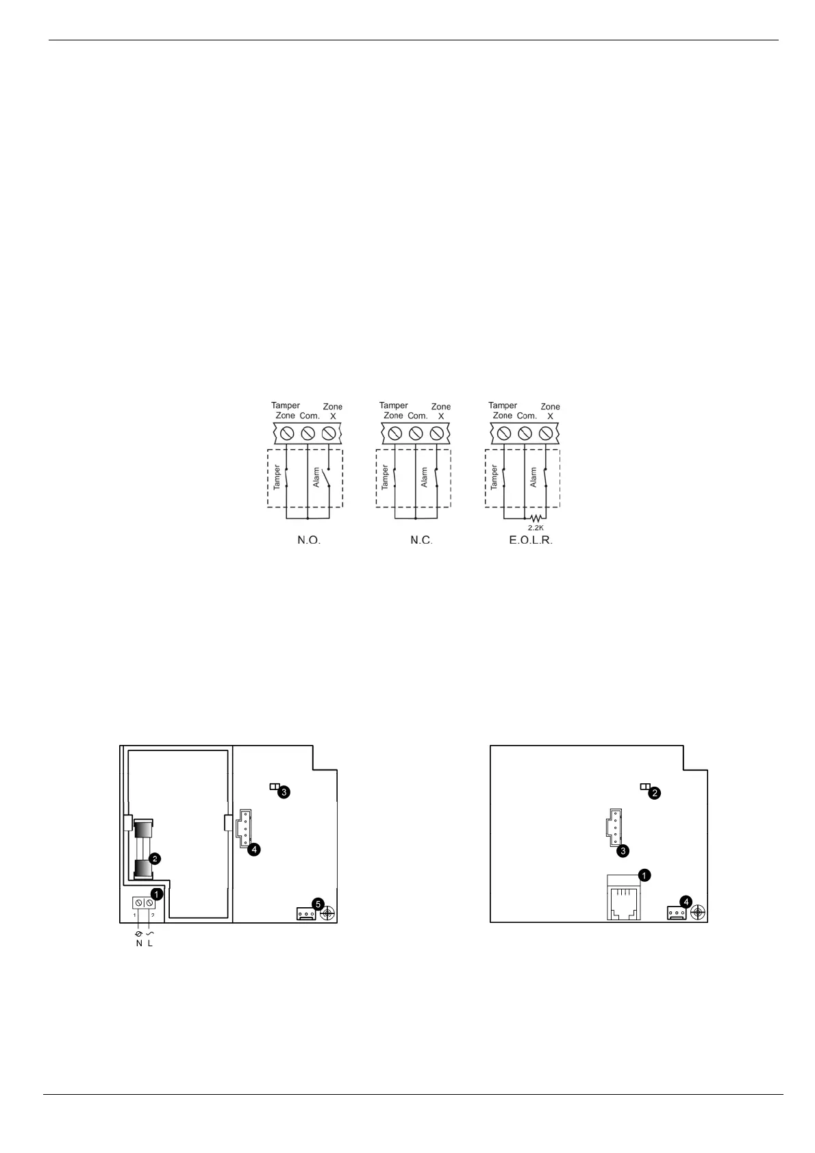
Loop Types
The control system supports the following Loop Types:
Normally Closed (N.C.) – restore on short, alarm on open.
Normally Open (N.O.) – alarm on short, restore on open.
End of Line Resistor (E.O.L.R.) – alarm on short, restore on normal, alarm on open.
The zone Loop Types must be defined accordingly at each zone’s programming parameters – see p 47, 7.3.10 Loop
Type (hardwire zones 1 to 8).
Figure 1-6: Loop Types
1.4.3. Home Automation Module
The Home Automation module provides the system with an interface to the power-line network, enabling control over
16 home automation units employing the X10 protocol via an external or internal Power-line Interface (PLI), depending
on your system configuration. Figure 1-7 shows the HA module used in the systems with internal PLI (for use in 220V,
50Hz A.C. power systems), and Figure 1-8, with external PLI (for use in 110V, 60Hz A.C. power systems).
Figure 1-7: Home Automation Module (Internal PLI Module) Figure 1-8: Home Automation Module (External PLI Module)
1. Power-line terminal connections to Main
Board (1 - Neutral; 2 - Live)
2. Fuse
3. LED Indicator
4. Flash programming connector
5. Interface connector to Main Board
1. External PLI connector
2. LED indicator
3. Flash programming connector
4. Interface connector to Main Board