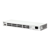
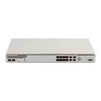
MES53xx, MES33xx, MES23xx Ethernet Switch Series 19
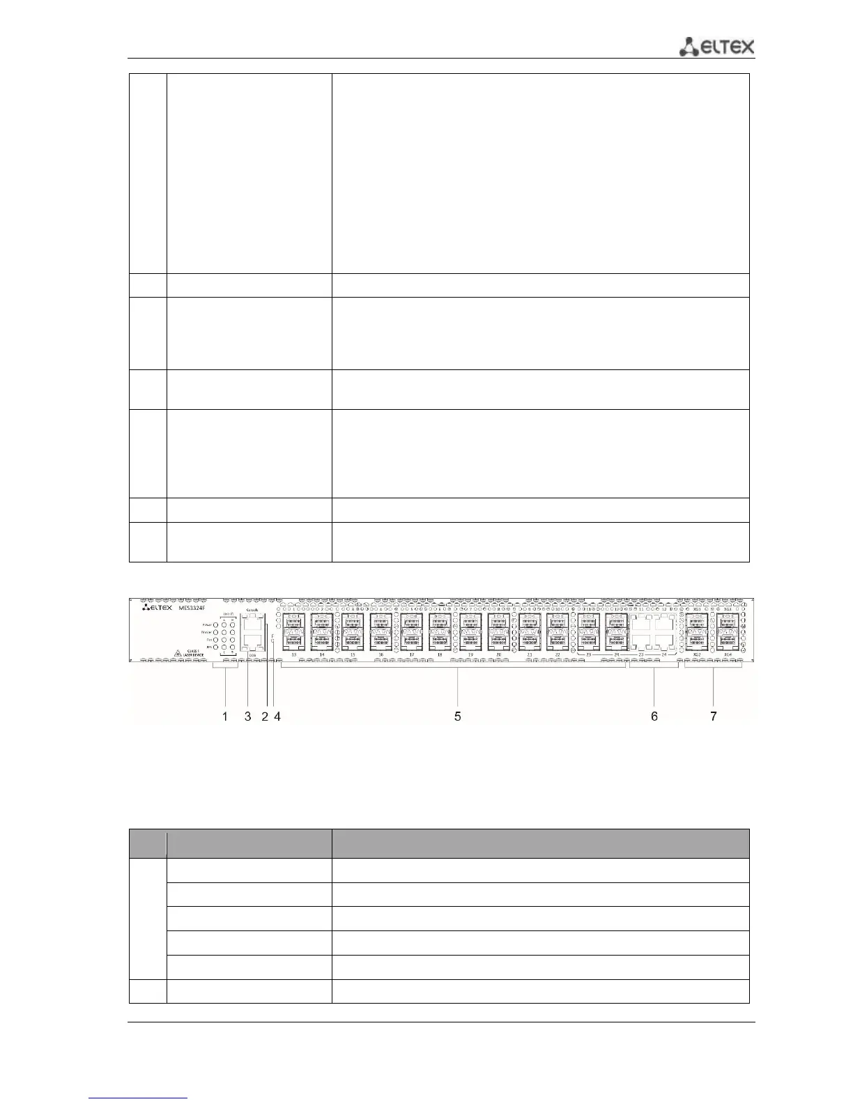
Console port for local management of the device.
Connector pinning:
1 not used
2 not used
3 RX
4 GND
5 GND
6 TX
7 not used
8 not used
9 not used
Soldering pattern of the console pattern is given in Appendix B
Out-of-band 10/100/1000 Base-T (RJ-45) port for remote device
management.
Management is performed over network other than the transportation
network.
10/100/1000 Base-T (RJ-45) port for remote device management over the
transportation network.
Functional key that reboots the device and resets it to factory default
configuration:
- pressing the key for less than 10 seconds reboots the device.
- pressing the key for more than 10 seconds resets the device to factory
default configuration.
Slots for 10G SFP+/ 1G SFP transceivers.
Slots for XLG1-XLG4 transceivers.
Transceivers 40GQSFP.
Figure 2. MES3324F, front panel
Table 2.11 lists connectors, LEDs and controls located on the front panel of the MES3324F switch.
Table 2.11. Description of MES3324F connectors, LEDs and front panel controls
Indicator of the stack unit number.
Device operation mode LED (master/slave).
Console port for local management of the device.
 Loading...