Installing components
25
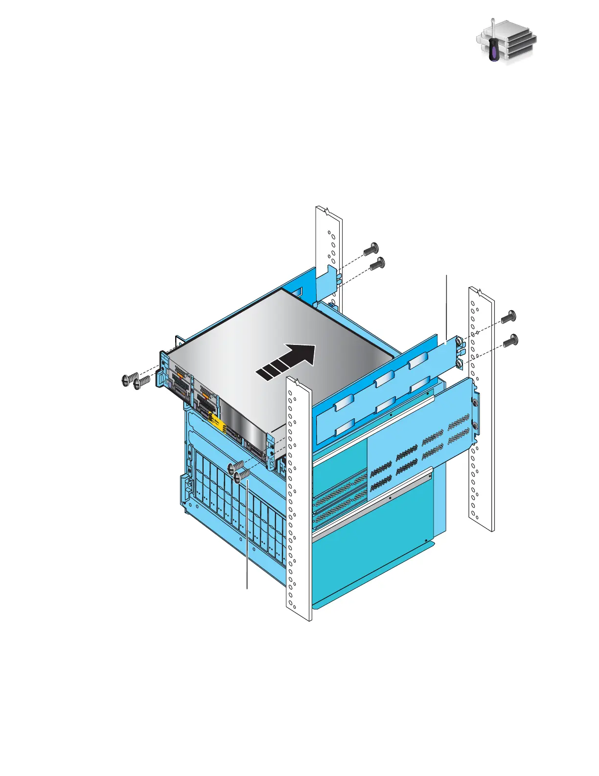
Installing optional blade enclosure 1
4. Slide blade enclosure 1 into the 2U adjustable rail above blade enclosure 0 as shown in
Figure 13.
5. Working in a diagonal pattern bottom left and top right, bottom right and top left, attach, but
do not tighten, the component by inserting the four screws through the blade enclosure, the
cabinet rail, and into the ganged rail as shown in Figure 13.
6. If there are no more components to insert, tighten all the screws.
Figure 13 Installing blade enclosure 1
2U adjustable
rail
Front
AA
ACA
C
ACAC
ACA
C
ACA
C
B
Blade enclosure 1
B
2 screws
per side
2 screws
per side
A
ACA
C
B
ACA
C
ACA
C
ACA
C
Blade Enclosure 1
Remove Prior to powering up equipment
046-003-752_A01
VNX-000247