40
EMC VNX5500 File Installation Guide
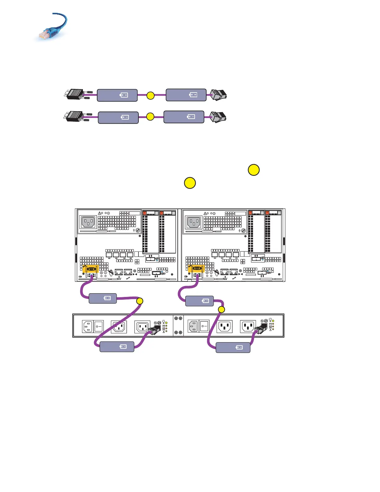
Cabling the standby power supply to SP serial port
1. Locate the cables as shown in Figure 28. These cables have RJ45 connections on one end and
a 9-pin mini-connector on the other.
Figure 28 SPS cables
2. Connect SPS A to the SP A serial port as shown in Figure 29.
3. Connect SPS B to the SP B serial port.
Figure 29 Cabling SPs to the SPS
A
B
SPS A
SP A
SPS B
SP B
VNX-000219
SPS B
X4
2
3
4
5
6Gb
SAS
8Gb
bre
1
0 X4
6Gb SAS
0
1
2
3
X4
2
3
4
5
6Gb
SAS
8Gb
bre
1
0 X4
6Gb SAS
0
1
2
3
B
A
Power
Power
Switch
Power
Power
Switch
Standby power supply
Disk processor enclosure
SPS A
SPS B optional
B
SP B
SP A
SPS B
SPS A
A
VNX-000220