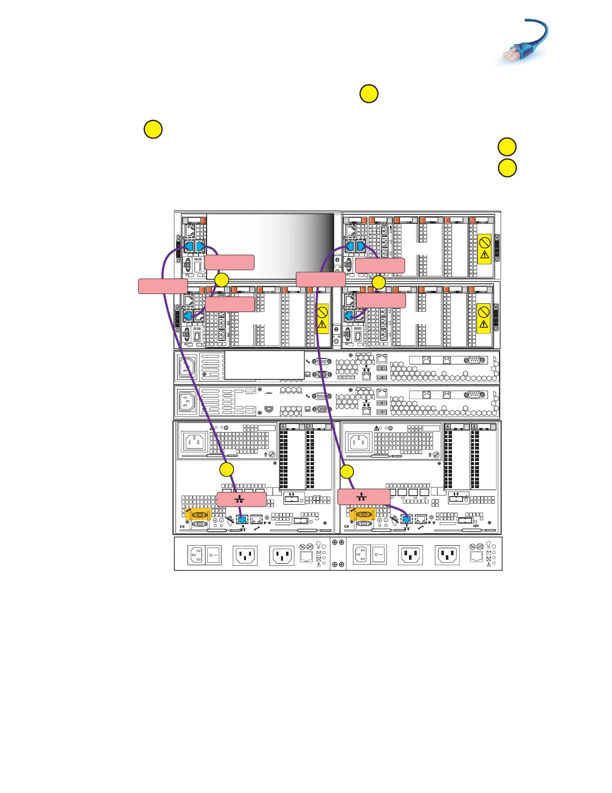
Cabling SPs to the blade management modules
39
2. Connect SP A MGMT to the highest blade enclosure, which is blade enclosure 1 port 0 on the A
side in the example shown in Figure 27 on page 39.
3. Connect SP B MGMT to the highest blade enclosure, which is blade enclosure 1 port 0 on the B
side.
4. Cross-connect blade enclosure 0 port 0 to blade enclosure 1 port 1 on the A side.
5. Cross-connect blade enclosure 0 port 0 to blade enclosure 1 port 1 on the B side.
Figure 27 Cabling SPs to two blade enclosures
0
123
00
1 2 3
0
1
2 3
0
1
2 3
0
1 2 3
Blade 3
Power
Power
Switch
Power
Power
Switch
X4
2
3
4
5
6Gb
SAS
8Gb
bre
1
0 X4
6Gb SAS
0
1
2
3
X4
2
3
4
5
6Gb
SAS
8Gb
bre
1
0 X4
6Gb SAS
0
1
2
3
Serial
console
MGMT
CS
B
MODEM socket
VGA plug
A
IPMI port
Serial
console
MGMT
CS
B
MODEM socket
VGA plug
A
IPMI port
Control Station 0
CS 1 optional
SP B
SP A
0
123
0
1
2 3
0
1
2 3
0
1 2 3
0
1 2 3
Blade 2
OptionalOptional
Control Station 1
1
2
0
1
2
0
0
123
0
1
2 3
0
1
2 3
0
1
2 3
0
1 2 3
Blade 3
0
123
0
1
2 3
0
1 2 3
0
1 2 3
0
1 2 3
Blade 4
1
2
0
2
SP B MGMT
B
Blade Encl 1
MMB Port 0
Blade Encl 1
MMB Port 1
Blade Encl 0
MMB Port 0
A
SP A MGMT
Blade Encl 1
MMA Port 1
Blade Encl 0
MMA Port 0
C
D
Blade Encl 1
MMA Port 0
0
1
Blade
enclosure 1
Blade
enclosure 0
DPE
SPS
B Side
A Side
VNX-000255