52
EMC VNX5500 File Installation Guide
Connect SAS DPE and DAE cables
In this example, two DAEs are being added. This example illustrates connecting one DAE to each
of the ports available on the DPE. Each DAE has two Link Control Cards (LCC), designated A or B.
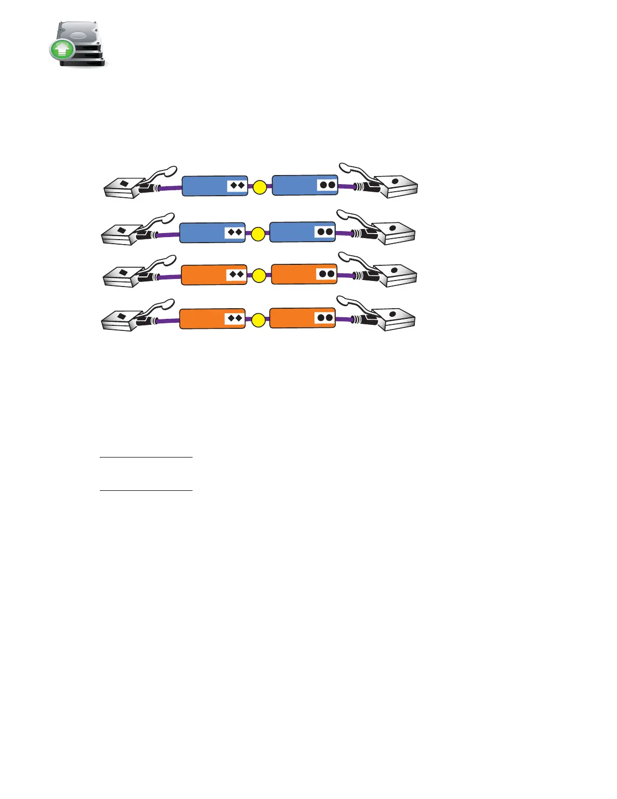
1. Locate one pair of cables for each DAE as shown in Figure 42.
Figure 42 SAS cables for the first two DAEs
The SAS ports on the DPE are labeled 0 and 1. Port 0 is connected internally to the SAS expander
that connects all the internal DPE disks. Since Port 0 is already connected internally to the DPE
disks, the first DAE is connected to Port 1 to balance the load on the SAS ports. The second DAE is
connected to Port 0.
Note: The
VNX5500 Hardware Information Guide
provides examples of how to cable DAEs in your
VNX5500 for interleaved or stacked environments.
The VNX5500 supports additional buses for the storage array. For environments with high
bandwidth requirements, one of the I/O module slots on each SP can be used for a SAS I/O
module that provides four additional BE buses. See the
VNX5500 Hardware Information Guide
for
information on cabling additional buses.
VNX-000268
D
C
A
B
LCC B
LCC A
LCC A
LCC B
SP B SAS 0
SP A SAS 0
SP A SAS 1
SP B SAS 1