Assembling the DAEs
53
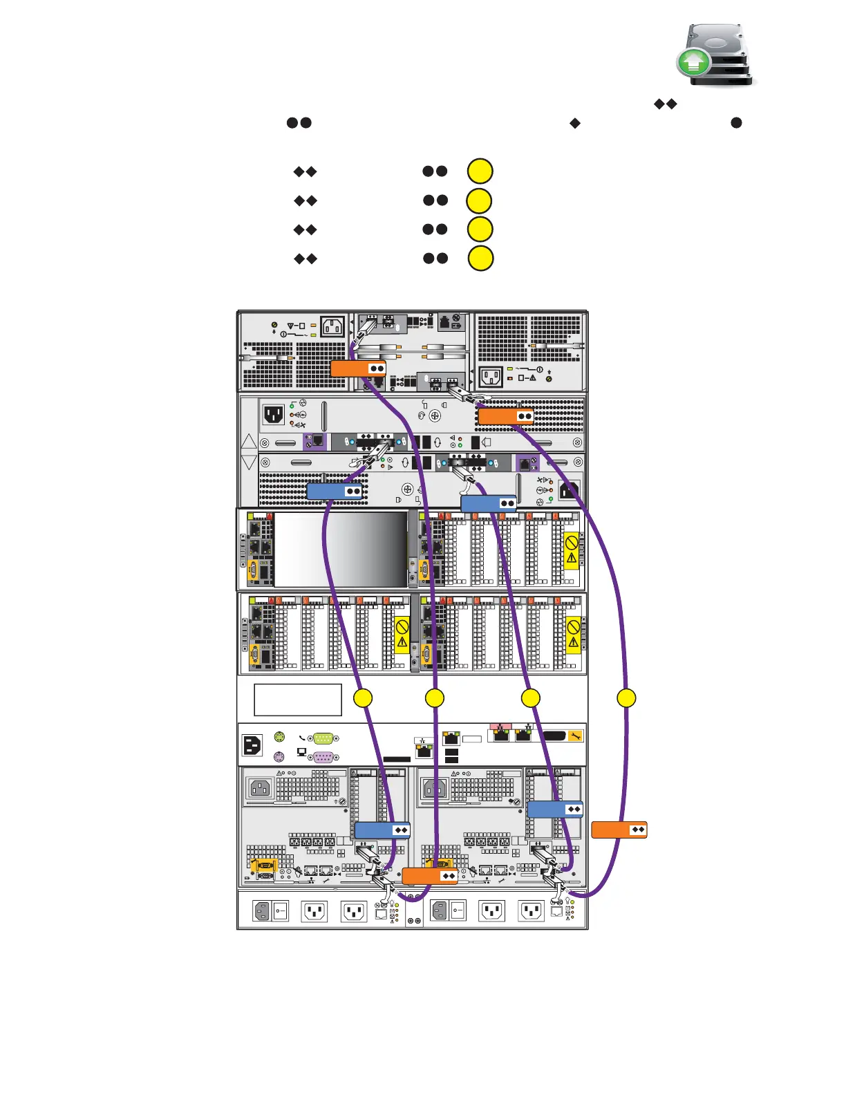
For steps 2 to 5, connect the following cables by matching the double diamonds on the DPE
and the double circles on the DAEs with the single diamonds and the single circles
on the cable connectors as shown in Figure 42 on page 52. Ensure that the cables lock into place.
2. Connect SP A SAS 1 to DAE 1 LCCA .
3. Connect SP B SAS 1 to DAE 1 LCCB .
4. Connect SP A SAS 0 to DAE 2 LCCA .
5. Connect SP B SAS 0 to DAE 2 LCCB .
Figure 43 Connecting SAS cables
A
CS
B
MGMT
#
#
A
B
##
X4
6Gb SAS
#
X4
6Gb SAS
2
3
4
5
B
Power
Power
Switch
Power
Power
Switch
SP B
6Gb
SAS
8Gb
bre
1 X4
6Gb SAS
X4
2
3
4
5
6Gb
SAS
8Gb
bre
1
0 X4
6Gb SAS
A
SP A
0 X4
B
A
DB
OptionalOptional
Control Station
LCC B
LCC B
LCC A
SP B SAS 1
SP A SAS 1
Blade enclosure 1
(optional) 2U
DAE 2
2U 25 disk
(optional)
DAE 1
3U 15 disk
(optional)
DPE 3U
SPS 1U
Blade enclosure 0
2U
Control Station1
(optional) 1U
Control Station 0
1U
Rear
6 Gb
SAS
X4
6 Gb
SAS
X4
LCC A
SP A SAS 0
SP B SAS 0
A
C
VNX-000257