Cabling SPs to the blade management modules
37
Cabling SPs to the blade management modules
If you have two blade enclosures, go to “Cabling for two blade enclosures” on page 38
Cabling for one blade enclosure
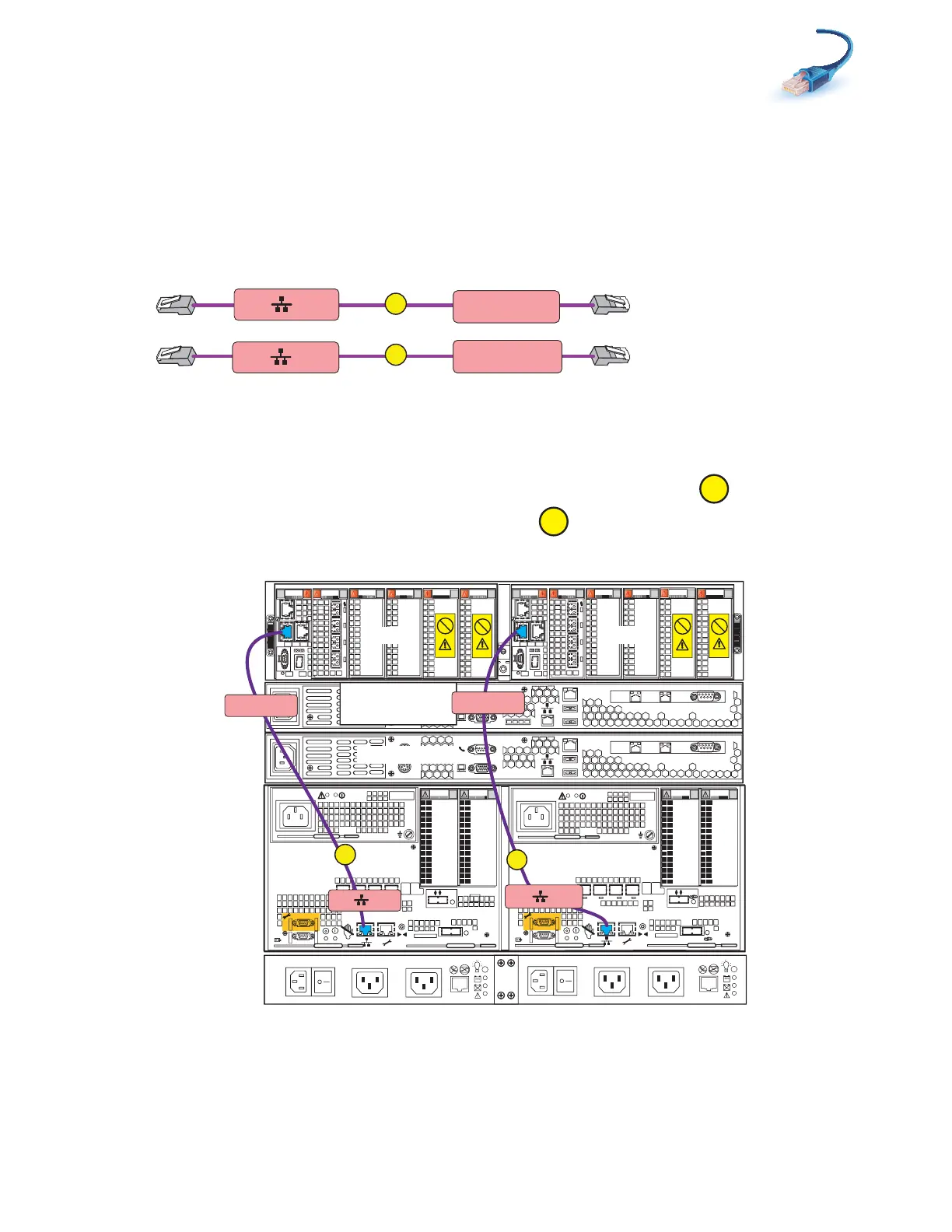
1. Locate the cables as shown in Figure 24.
Figure 24 Blade enclosure cables
2. Connect SP A MGMT to blade enclosure 0 port 0 as shown in Figure 25.
3. Connect SP B MGMT to blade enclosure 0 port 0.
Figure 25 Cabling SPs to one blade enclosure
A
B
SP A MGMT
Blade Encl 0
MMA Port 0
SP B MGMT
Blade Encl 0
MMB Port 0
VNX-000213
0
123
00
1
2 3
0
1
2 3
0
1
2 3
0
1 2 3
Blade 3
Power
Power
Switch
Power
Power
Switch
X4
2
3
4
5
6Gb
SAS
8Gb
bre
1
0 X4
6Gb SAS
0
1
2
3
X4
2
3
4
5
6Gb
SAS
8Gb
bre
1
0 X4
6Gb SAS
0
1
2
3
Serial
console
MGMT
CS
B
MODEM socket
VGA plug
A
IPMI port
Serial
console
MGMT
CS
B
MODEM socket
VGA plug
A
IPMI port
Control Station 0
CS 1 optional
SP B
SP A
0
123
0
1
2 3
0
1
2 3
0
1 2 3
0
1 2 3
Blade 2
OptionalOptional
Control Station 1
1
2
0
1
2
0
SP B MGMT
B
Blade Encl 0
MMB Port 0
A
SP A MGMT
Blade Encl 0
MMA Port 0
Blade
enclosure 0
DPE
SPS
B Side
A Side
VNX-000214