Removing mini-rack components
11
Removing mini-rack components
To remove the mini-rack components:
1. Remove the Control Station information label from the front of CS0 and attach it to the inside
cover of this manual. If you have a second optional Control Station (CS1), remove this Control
Station information label and attach it to the inside cover of this manual.
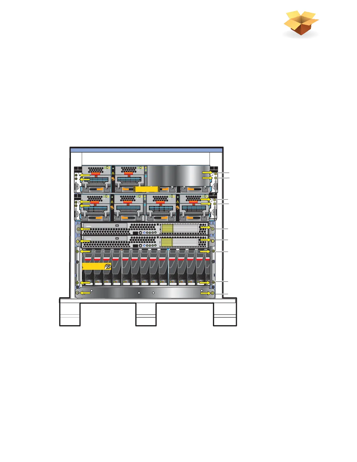
2. Remove only the screws (colored yellow in Figure 1) holding the components in the mini-rack.
The yellow colored arrows in Figure 1 point you to which screws to remove.
3. Retain these removed screws for later assembly of the components into a site rack.
Figure 1 Mini-rack components
SAS SAS SAS SAS SAS SAS SAS SAS SAS SAS SAS SAS SAS SAS SAS
Will Make the Array Unusable
Caution: Array Software on drives 0-3. Removing or relocating them
AC
AC
AC
AC
B
PS B0
PS B1
CPU B
DVD
Control Station 1
DVD
Control Station 0
B
PS B0
PS B1
CPU B
AC
AC
AC
AC
B
PS B0
PS B1
CPU B
PS A0
PS A1
CPU A
A
Blade Enclosure 1
Remove Prior to powering up equipment
046-003-752_A01
Front
7 Disk processor enclosure
6 Control Station 0
5 Control Station 1 (optional)
3 Blade enclosure 0
4
9 Standby power supply
8 Disk processor enclosure
Mini-rack
1 Blade enclosure 1 (optional)
2
PS A0
PS A1
CPU A
A
VNX-000244