12
EMC VNX5500 File Installation Guide
Some of the components in the mini-rack are heavy and may require two people. If needed, use
an appropriate lifting device (mechanical lift).
These components are not interchangeable. Ensure that you install the components in the
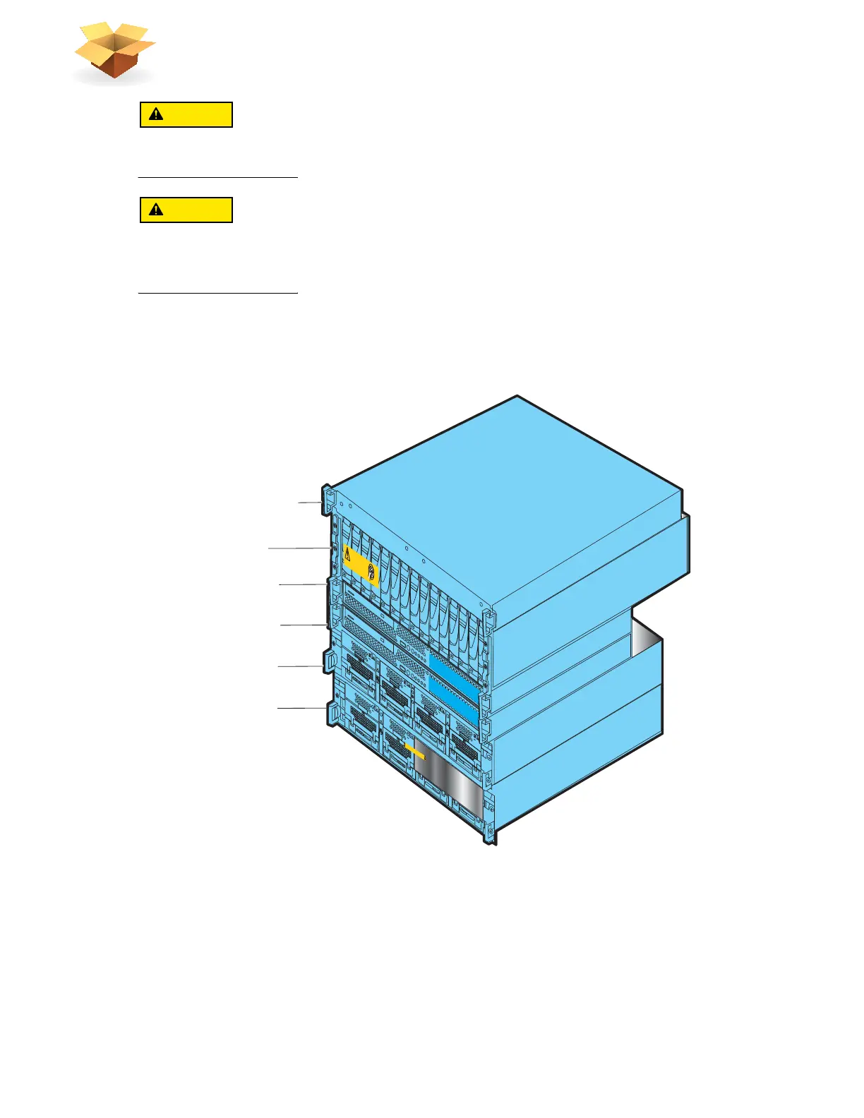
following order: SPS, DPE, CS0, CS1 (optional), blade enclosure 0, and blade enclosure 1
(optional). Otherwise, your storage system will not operate properly.
4. Starting from the top of the mini-rack, carefully slide the components out of the mini-rack and
stack them in the reverse order of how they will be placed in your cabinet as shown in Figure 2.
Be sure to place the first removed component on an antistatic floor or workbench pads.
Figure 2 Removed mini-rack components
5. If blade enclosure 1 was included in the mini-rack, unscrew and remove the 2U adjustable
rails separately.
6. Unscrew all front and rear screws and remove the 8U ganged rails from the mini-rack as shown
in Figure 3 on page 13.
7. Retain all the removed rails and screws for later assembly of the rails into a site rack.
Blade enclosure 1
AA
ACA
C
ACA
C
ACA
C
ACA
C
B
Will Make the Array Unusable
Caution: Array Software on drives 0-4. Removing or relocating them
Control Station 0
DV
D
DV
D
Control Station 1
Standby power supply
Disk processor enclosure
Blade enclosure 0
A
A
C
A
C
AC
AC
B
1 Standby power supply
2 Disk processor
enclosure
5 Blade enclosure 0
3 Control Station 0
4 Control Station 1
(optional)
Front
VNX-000758
Blade Enclosure 1
Remove Prior to powering up equipment
04
6
-003-75
2
_
A
01
6 Blade enclosure 1
(optional)
 Loading...

