2-29
Installation
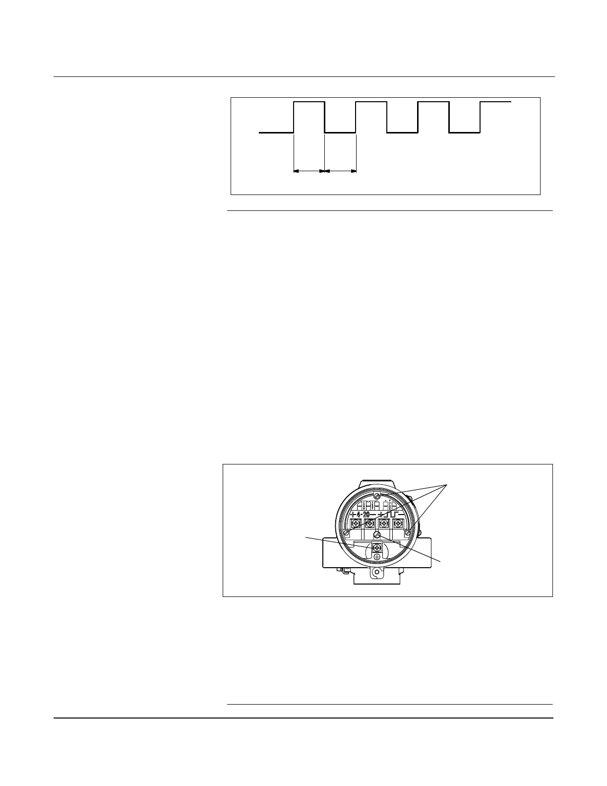
Figure 2-20. Example: The pulse output will maintain a 50 percent duty cycle for all frequencies
NOTE
When using pulse output, be sure to follow these precautions:
•Shielded twisted pair is required when the pulse output and 4–20 mA
output are run in the same conduit or cable trays. Shielded wire will
also reduce false triggering caused by noise pickup. Wiring should be 24
AWG or larger and not exceed 5,000 ft. (1500 m).
•Do not connect the powered signal wiring to the test terminals. Power
could damage the test diode in the test connection.
•Do not run signal wiring in conduit or open trays with power wiring,
or near heavy electrical equipment. If needed, ground signal wiring at
any one point on the signal loop, such as the negative terminal of the
power supply. The electronics housing is grounded to the spool.
•If the flowmeter is protected by the optional transient protector, you
must provide a high-current ground connection from the electronics
housing to earth ground. Also, tighten the ground screw in the bottom
center of the terminal block to provide a good ground connection.
Figure 2-21. The Transient Terminal Block
•Plug and seal all unused conduit connections on the electronics
housing to avoid moisture accumulation in the terminal side
of the housing.
•If the connections are not sealed, mount the flowmeter with the
conduit entry positioned downward for drainage. Install wiring with a
drip loop, making sure the bottom of the drip loop is lower than the
conduit connections or the electronics housing.
50% Duty Cycle
8800-0546a
Transient Terminal
Block Ground Screw
Captive Screws
Housing Ground
8800-0000A03D