56 100-412-182 REV. 06
In the event the system is to be installed in a high dust environment, the use of a fan filter
kit (101-063-614) is required.
See Figure 5.2 Power Supply Dimensional Drawing for a dimensional drawing of the
2000Xd Power Supply.
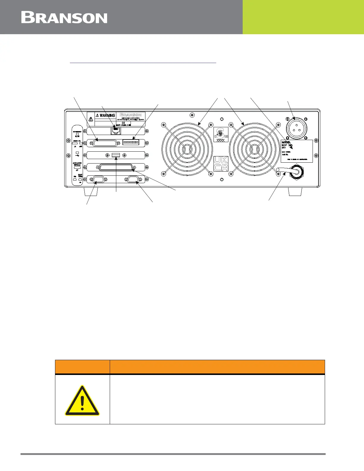
Figure 5.8 Connections on Rear of Power Supply
The cable lengths are limited based on the operating frequency of the welding system.
Performance and results can suffer if the RF cable is crushed, pinched, damaged or
modified. Contact your Branson Representative if you have special cable requirements. In
some cases, remote operation from a User I/O or a Remote Terminal can be used to solve
a distance limitation.
5.5.3 Input Power (Main)
The system requires single-phase input power, which you connect to the Power Supply
using the integral power cord. Nominal 120 volt units have a NEMA5-15P plug on the cord,
and nominal 200-240 volt units come with a twist-type locking connector, supplied in the
box with the Power Supply.
Refer to the unit’s Model Data Tag to be sure of the power rating of the Model in your
system.
5.5.4 Output Power (RF Cable)
Ultrasonic Energy is delivered to a screw-on MS receptacle connection on the rear of the
Power Supply, which is connected to the Actuator by an SHV connector.
Fans
RF Connector
(ultrasonic energy out)
Model Data Tag
Ethernet Connector
DIP Switch for User I/O
User I/O Connector
Power Cord
r
Actuator Interface Connector
Serial Port (RS-232) Connector for Host Computer
USB Connector
VGA Connecto
WARNING General Warning
Never operate the System with the RF Cable disconnected or if the RF
Cable is damaged.