58 100-412-182 REV. 06
5.5.6 Start Switch Connection (Automation)
A Branson actuator requires two start switches and emergency stop connection. For the
2000X Micro Actuator it is required that the user makes his own start switch/E-stop
connections, as follows:
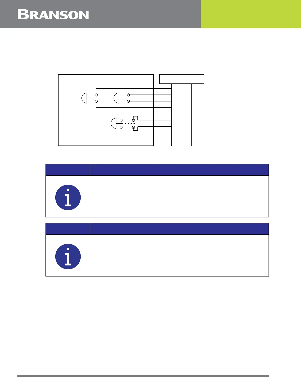
Figure 5.10 Start Switch Connection Codes
BASE/START is the DB-9 female connection on the back of the interface box. Your cable
requires a male DB-9 (D-shell) connector.
PB1 and PB2 are two normally open start-switches which must be operated
simultaneously to start the welding cycle. These must be closed within 200 milliseconds of
each other, or error message “Start Sw Time” will display. This doesn’t require a reset, but
for the next cycle, switches must be within time limit to preclude re-occurrence of error
message. Refer to Note above.
NOTICE
Solid State devices may not be used in lieu of mechanical start
switches providing their leakage current does not exceed 0.1mA.
NOTICE
Start Switches PB1 and PB2 must be closed within 200 milliseconds
of each other, and remain closed until the WELD ON signal is active,
to effect a start condition.
BASE/START
EMER
STOP
START SWITCHES
PB1PB2
1
2
3
4
5
6
7
PB2RTN
9
8
Color Codes
PB1RTN
PB1SRC
PB2SRC
ESTOPSRC
ESTOPSRC
ESTOPRTN
ESTOPRTN
N/C
Blue
Black
White
Orange
Purple
Yellow
Red
Green
Brown