100-412-182 REV. 06 49
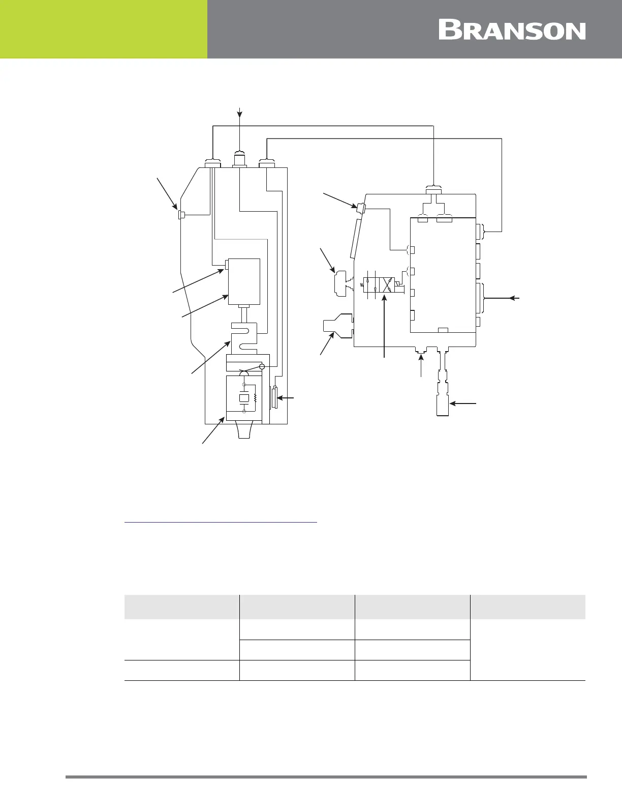
Figure 5.4 Block Wiring Diagram
5.4.3 Electrical Input Power Ratings
Plug the Power Supply into a single-phase, grounded, 3-wire, 50 or 60 Hz power source.
Table 5.5 Input Power requirements lists the current and fuse ratings for the various
models.
The ground screw on the rear of the Actuator must be connected to earth ground with #8
gauge wire.
S-BEAM
CYLINDER
ULS
POWER
INDICATOR LIGHT
CONTROL
CABLE
ENCODER
CABLE
RF
CABLE
(FROM P/S)
P/S
SIGNALS
REMOTE
PNEUMATICS
ENCODER
BASE/
START
INTERFACE
BOARD
POWER
INDICATOR LIGHT
SOLENID
VALVE
PL
J66_A
SV3
J63_A
J67
SB
J64
PV
J62_A
SV1
J65
LC
J61_A
ULS
J85_A
J70_A
J69_A
J60
ENCODER
CONVERTER
MPS/GDS
J75_A
ACTUATOR
INTERFACE CABLE
(FROM P/S)
DOWN SPEED
CONTROL
AIR PRESSURE
REGULATOR
AIR
INLET
SILENCER
Table 5.5 Input Power requirements
Model Input Voltage Maximum Current Fuse
40 kHz/800 W
100V-120V 10A
20 A200V-240V 5A
40 kHz/400 W 100V-120V 5A