40 100-412-182 REV. 06
Linear Encoder
The encoder measures the distance the horn has travelled. Depending on the Power
Supply settings, it can:
• Allow for distance welding
• Detect improper setup controls
• Monitor the quality of the weld
• Decrease cycle time by generating signal to initiate indexing of material equipment before horn is
fully retracted
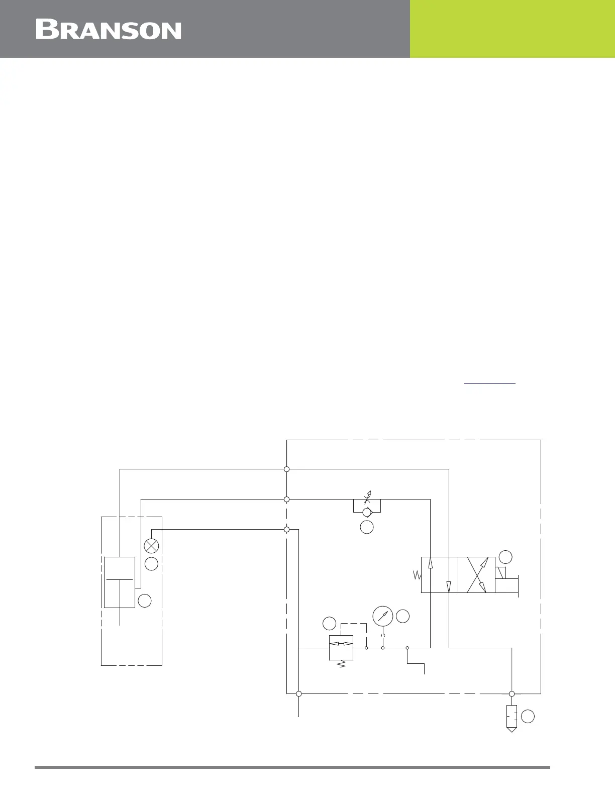
Pneumatic System
The pneumatic system is contained within the Actuator and the interface box. The system
consists of:
1. Air cylinder
2. Pressure indicator
3. Pressure regulator
4. Pressure gauge
5. Primary solenoid valve
6. Down speed flow control valve
7. Silencer
The horn’s rate of descent (downspeed) is adjusted at the front of the interface box using
the Downspeed control knob. The rate of ascent is fixed. Refer to Figure 4.1 for a
schematic of the pneumatic system.
Figure 4.1 2000X Micro Actuator Pneumatic System
ACTUATOR
CYL.
INTERFACE BOX
DOWN SPEED
CONTROL
AIR
INLET
REGULATOR
METERING
INSERT
BA
PRIMARY
SOL. VALVE
E
PRESSURE
INDICATOR
1
IN
PRESSURE
GAGE
SILENCER
INTERFACE
BOARD
3
2
4
5
6
7