100-412-182 REV. 06 53
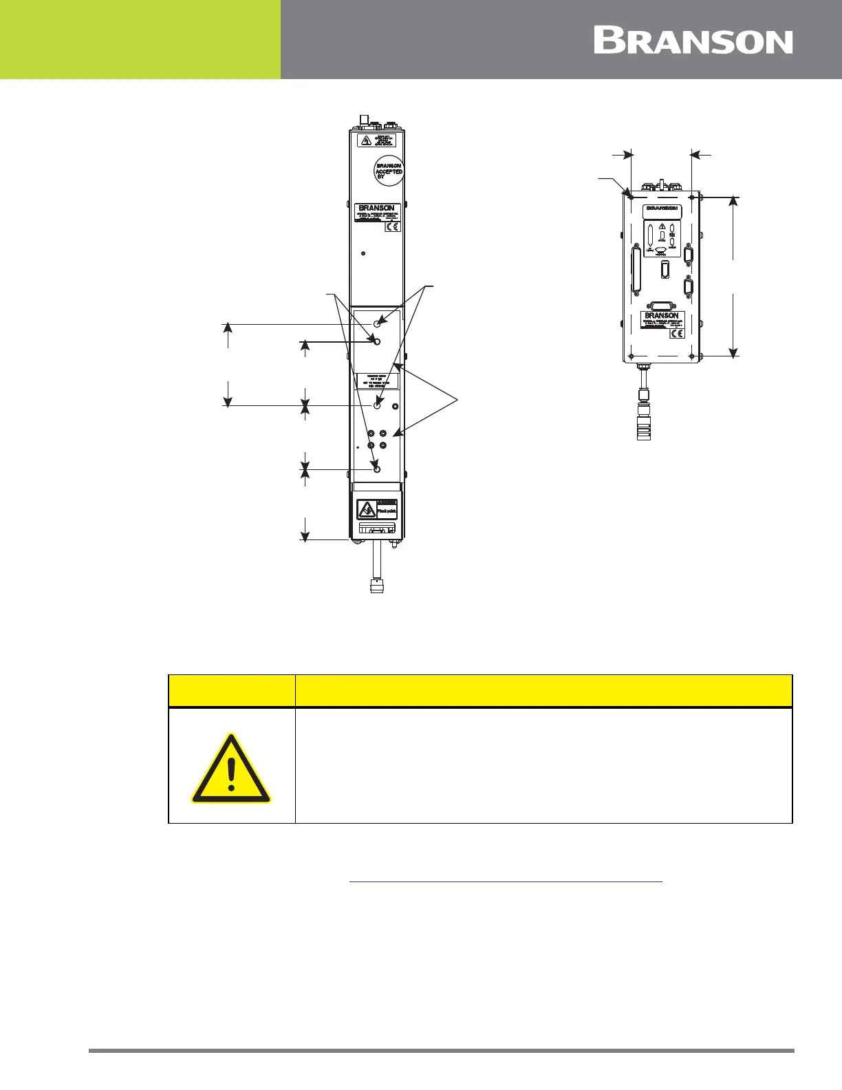
Figure 5.5 Rear view of Actuator, showing Mounting Surface, Bolt and Guide Pin locations
4. Lift the Actuator assembly into position on your mount, and secure using the metric bolts
provided.
5. Mount your Interface Box using four M4 screws (nit provided with the Actuator). An optional
Interface Box mounting kit is available (kit 101-063-889). The kit consists of a mounting plate
and four M4 screws. See
Figure 5.6 Interface Box Mounting Plate (optional).
CAUTION General Warning
In the event you must use bolts of a different length, ensure that the
bolts extend more than 0.25 inch (6 mm) into the threads in the
Actuator housing, but less than 0.62 inch (15 mm).
3.135 in
79.63 mm
3.44 in
87.37 mm
3.135 in
79.63 mm
4 in
101.6 mm
5/16 in dowel pin
1/2 in deep max
(2 places)
M8 X 1.5 THDS
20 mm deep
(2 places)
Machined mounting
surfaces (2 places)*
*These two mounting surfaces are flat
within 0,004 in. (0,1mm) TIR, in a tolerance
zone of 10.8 x 2.6 in. (274.3 x 66 mm). The
surface to which the actuator is mounted
must also have the same flatness tolerance
3.1 in
78.74 mm
8.13 in
206.5 mm
M4 mounting
screws
(4 places)