54 100-412-182 REV. 06
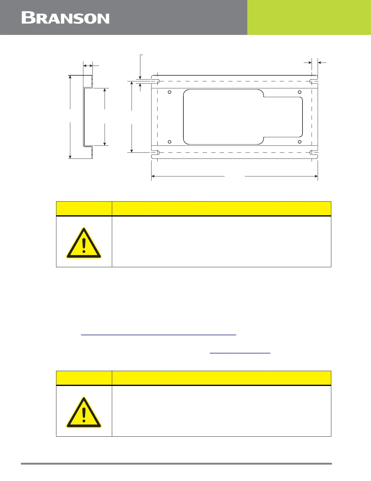
Figure 5.6 Interface Box Mounting Plate (optional)
6. Make all pneumatic and electrical connections between the Actuator and Interface Box.
5.5.1 Installing the Mechanical Stop
The mechanical stop limits the downward travel of the horn. To prevent equipment
damage, install and adjust the stop so that the horn will not contact your fixture when no
workpiece is in place.
To install the mechanical stop using the locking nut:
1. Using a 1/2 in wrench, hold through the locking nut inside the mechanical stop guard opening
(See
Figure 5.7 Mechanical Stop Installations and Adjustment)
2. Screw the mechanical stop, through the locking nut, into the Actuator
3. Adjust the mechanical stop, as described in Section
6.2.6 Mechanical Stop
4. Tighten the locking nut
CAUTION General Warning
Tubbing Connections and Control Cables between the Actuator and
Interface Box should be bound together as a bundle with cable ties to
secure the airlines.
.59 in
15 mm
3.6 in
91 mm
.38 in
9.6 mm
.25 in
6.3 mm
TYP
5.2 in
132 mm
10.4 in
264 mm
4.45 in
113 mm
CAUTION General Warning
If the Mechanical Stop locking nut is not tightened it may prevent the
carriage from returning to the home position.