100-412-182 REV. 06 55
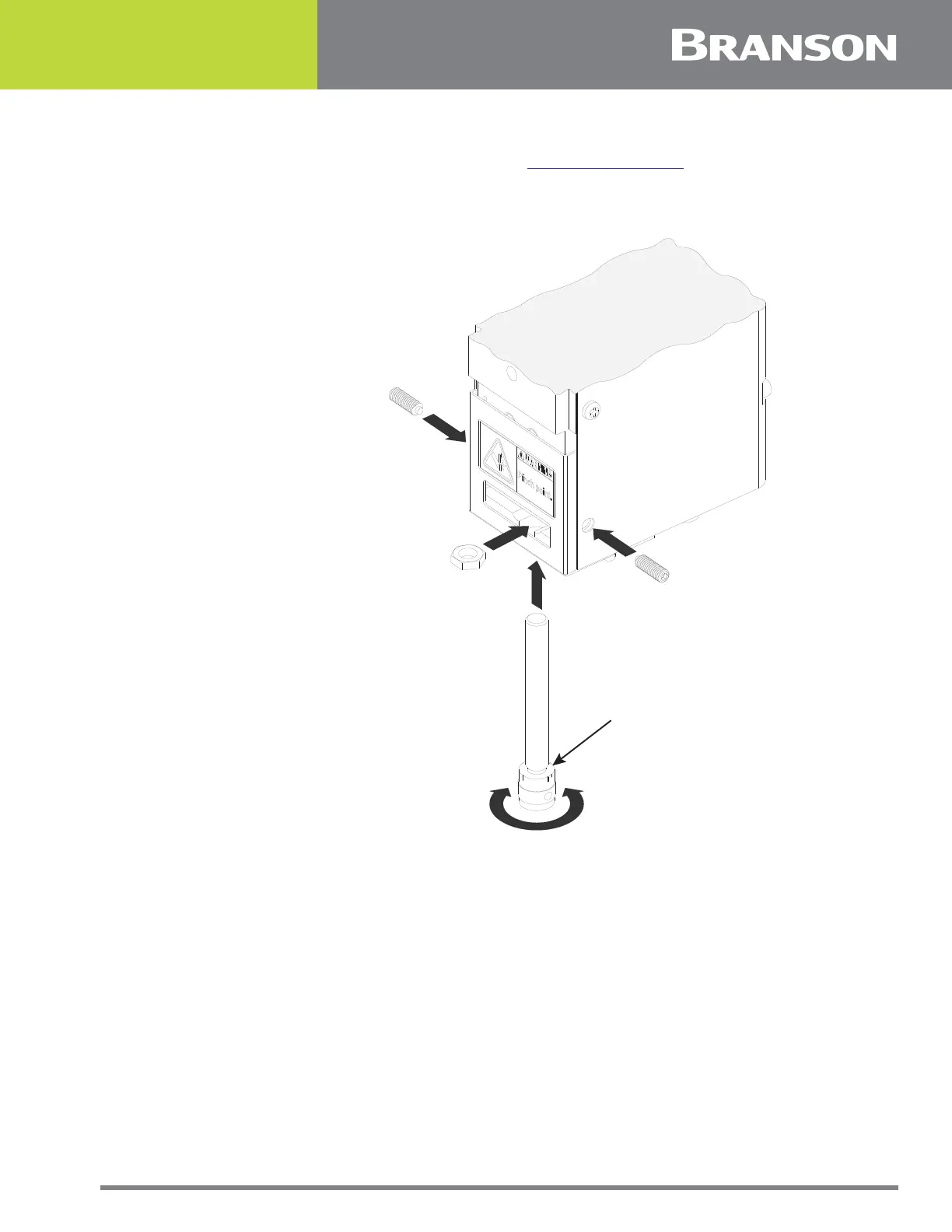
To install the mechanical stop using the set screws:
1. Screw the mechanical stop into the Actuator
2. Adjust the mechanical stop, as described in
6.2.6 Mechanical Stop
3. Use an M3 Hex key to insert the set screws and secure the mechanical stop
Figure 5.7 Mechanical Stop Installations and Adjustment
5.5.2 Mount the Power Supply
The Power Supply is designated to be placed on a workbench (rubber feet on bottom)
within cable-length limits of the Actuator, or it may be rack-mounted in a standard 19 -
inch Rack (using an optional rack mount handle kit). It has two rear - mounted fans
which draw cooling air from rear to front, which must be free from obstruction. Do not
place the Power Supply on the floor or in other locations that will allow dust, dirt or
contaminants to be drawn into the Power Supply.
The controls on the front of the Power Supply must be accessible and readable for setup
changes.
All electrical connections are made to rear of the Power Supply, which should be
positioned in your workspace with adequate clearance (approximately 4 inches or more on
either side, and 6 inches to the rear) for cable access and ventilation. Do not place
anything on top of the Power Supply case.
DECREASE
STROKE
LENGTH
INCREASE
STROKE
LENGTH
MECHANICAL STOP
LOCKING NUT
(DO NOT LOOSEN)
MECHANICAL STOP
ADJUSTING KNOB
SET SCREW
SET SCREW