MODEL 1000 SEP 2005
MAINTENANCE
5-29
5.5.8 Measure Vent Flow (MV)
You will need an accurate flow meter (Alltech Digital Flow Check™ Flowmeter or equivalent) for
this measurement.
To measure the MV vent flow, proceed as follows:
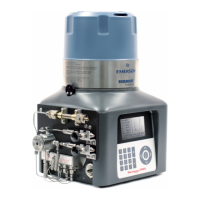
(1) Attach a flow meter to the vent output on the left side of the Analyzer marked "MV".
(2) The flow should measure 12-18 cc/min.
5.5.9 Analog Inputs
The analog inputs available to the GC Controller from the Model 1000 Analyzer and external
analyzers are shown in the following tables. (See also, drawing DE-20782 in Addendum 2, GC
Controller Drawings, this manual.)
Table 5-3. Analog Inputs to GC Controller (from Analyzer)
Board Acronyms:
- Terminal Board for Field Wiring at Controller (TB)
DETECTOR/PREAMPLIFIER SIGNAL OUTPUTS from ANALYZER
TB, J18, Terminal 11 common
TB, J18, Terminal 1 4-20 mA Gain channel 1 (8x1)
Measure between terminals 1(+) and 2(!), at TB, J18
TB, J18, Terminal 4 4-20 mA Gain channel 2 (8x4)
Measure between terminals 4(+) and 5(!), at TB, J18
TB, J18, Terminal 7 4-20 mA Gain channel 3 (8x32)
Measure between terminals 7(+) and 8(!), at TB, J18
TB, J18, Terminal 10 4-20 mA Gain channel 4 (8x256)
Measure between terminals 10(+) and 11(!), at TB, J18
 Loading...