MODEL 1000 SEP 2005
INSTALLATION AND SETUP
3-1
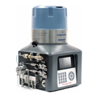
3.0 INSTALLATION AND SETUP
This section provides instructions for installing and setting up the Model 1000 Gas Chromatograph
system. This section is organized as follows:
Because the Model 1000 Gas Chromatograph system is available in different configurations,
not all of the instructions in this section may apply. In most cases, however, to install and set
up a Model 1000 Gas Chromatograph system, it is recommended that you follow the
instructions in nearly the same order as presented in this manual. (Also see Table 3-1 for a
summary of installation and setup steps.)
Precautions and Warnings ......................................... See Section 3.1
Hazardous Environments .............................................. 3.1.1
Power Source Wiring ................................................. 3.1.2
Signal Wiring ....................................................... 3.1.3
Electrical and Signal Ground ........................................... 3.1.4
Electrical Conduit ................................................... 3.1.5
Sample Systems Requirements ......................................... 3.1.6
Pre parati on ...................................................... See Section 3.2
Introduction ........................................................ 3.2.1
Site Selection ....................................................... 3.2.2
Unpacking the Unit .................................................. 3.2.3
Necessary Tools and Components ....................................... 3.2.4
Optional Tools and Components ........................................ 3.2.5
Installing the Analyzer ............................................ See Section 3.3
Point-to-Point Wiring Guide, Analyzer-Controller . . . . . . . . . . . . . . . . . . . . . . . . . . 3.2.3
Analyzer AC-Power Wiring ........................................... 3.3.1
Sample and Gas Lines ................................................ 3.3.3
Installing the GC Controller ........................................ See Section 3.4
Modbus Slave Address Setup (COM ID) Setup . . . . . . . . . . . . . . . . . . . . . . . . . . . . 3.4.1
Controller-Analyzer Wiring ............................................ 3.4.2
Controller-PC Wiring (Serial Connections) . . . . . . . . . . . . . . . . . . . . . . . . . . . . . . . . 3.4.3