MODEL 1000 SEP 2005
INSTALLATION AND SETUP
3-21
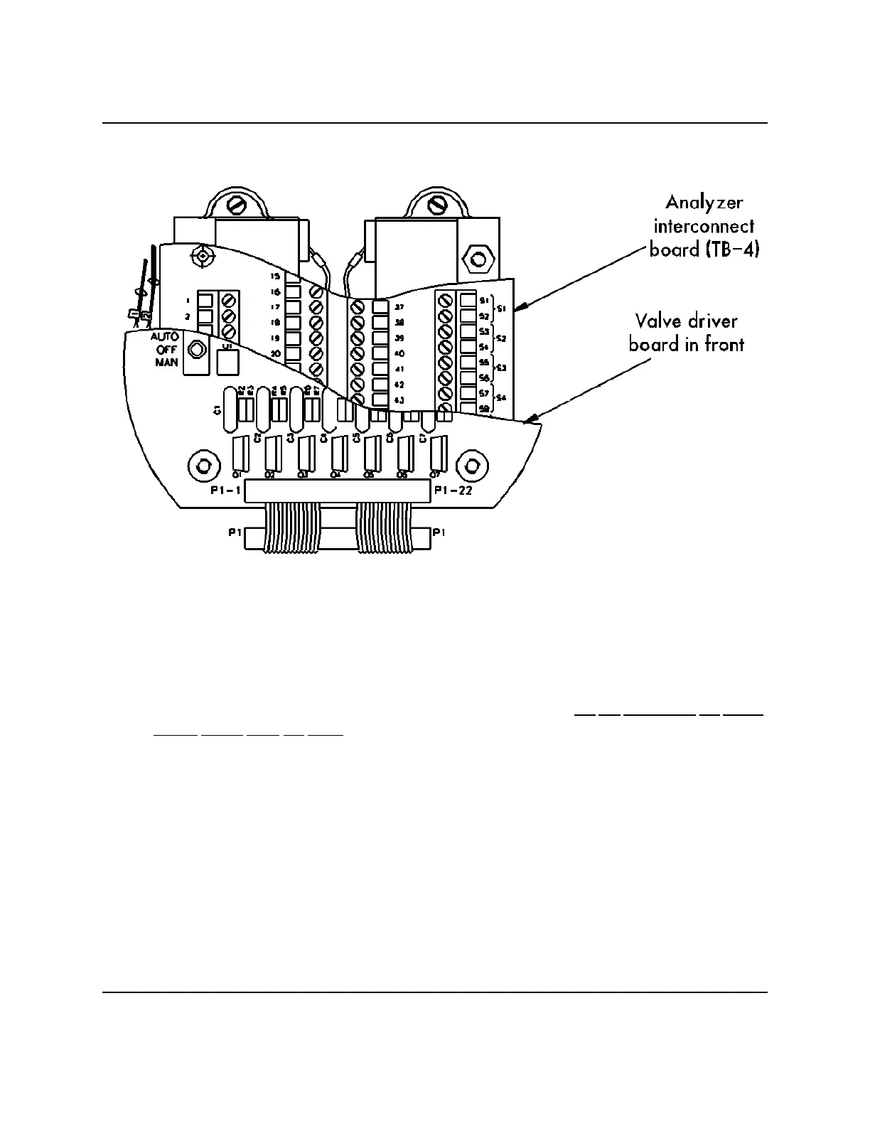
Figure 3-1. Behind the Valve Driver Board is the Interconnect Board Containing TB-4
(3) Loosen and remove the four (4) thumbscrews that hold the Valve Driver Board.
(4) Carefully edge the Valve Driver Board off the holding screws. Do not disconnect the Valve
Driver Board from the cable; merely let the board rest face down, secured by the cable (see
Figure 3-2).
(5) With the Analyzer TB-4 now exposed, connect thirteen of the Interconnect Cable’s fifteen
leads to terminals 11 through 23. See Table 3-2 and Figure 3-3 for purposes and destinations
of leads. Also see “CAUTION”, step (6)(a).
 Loading...