MODEL 1000 SEP 2005
INSTALLATION AND SETUP
3-37
(a) For the explosion-proof Controller, the front panel is secured by 16 screws. Remove
those screws first.
(b) Then carefully lower the front panel on its bottom hinges. The front panel is heavy,
so make sure it does not drop and cause damage.
(c) For the rack mount Controller, the rear of the enclosure is open; it allows access for
most field wiring procedures without removing the enclosure.
(4) Locate the GC Controller's Terminal Board for Field Wiring (TB). The TB is attached to the
GC Controller's card cage assembly, facing the enclosure's front panel. (In the rack mount
Controller, the TB faces outward toward the rear of the enclosure.)
(5) Route the Analyzer-Controller Interconnect Cable appropriately, especially in the case of the
purged Controller enclosure.
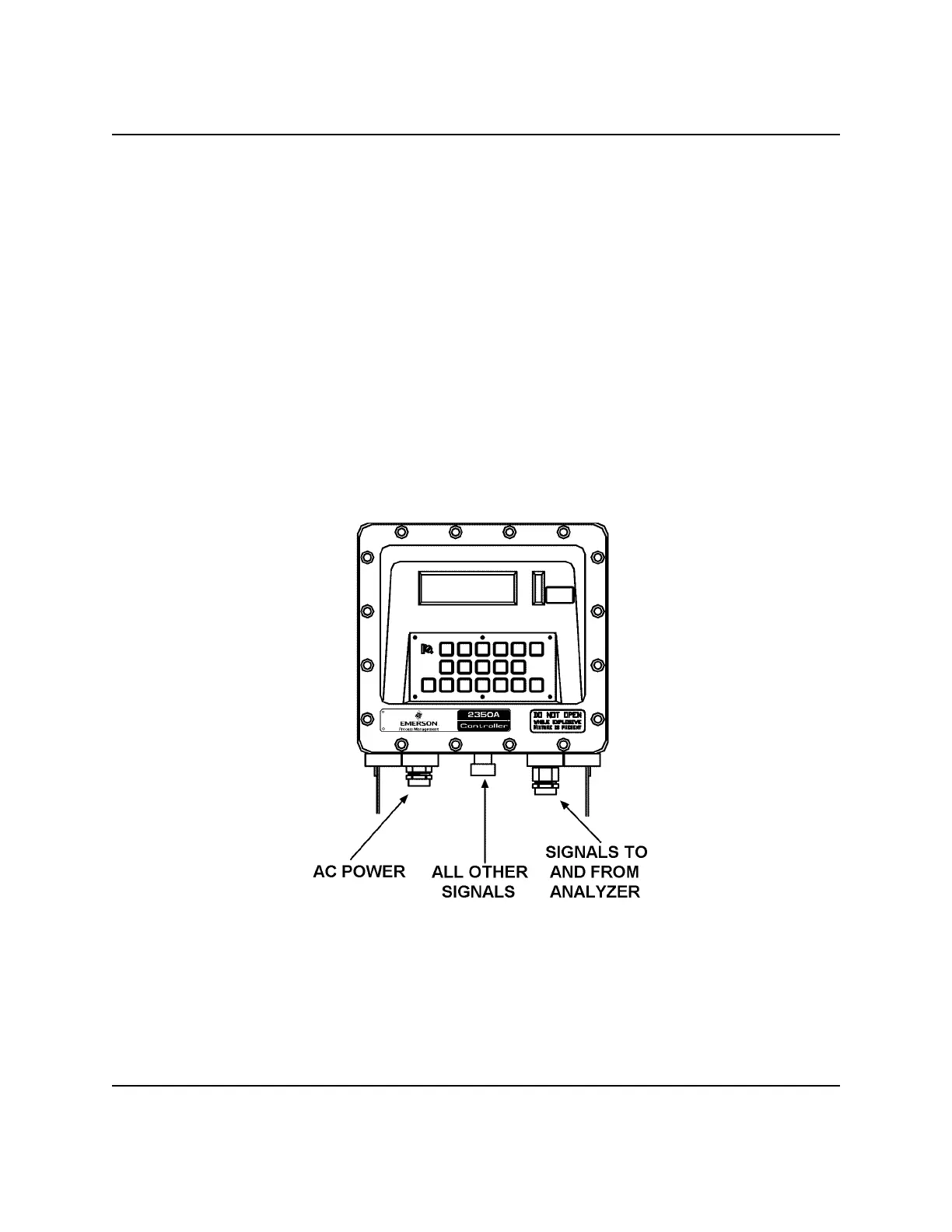
Figure 3-6. Separate Conduit Entries for Cable In/Out of GC Controller
(6) Make Interconnect Cable wiring connections to the GC Controller TB as listed earlier (see
Section 3.3.1, Table 3-2).
 Loading...