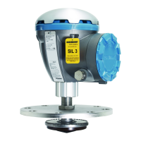
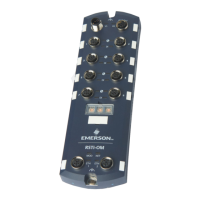
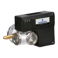
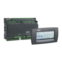
Figure 3-12: Example of Rosemount Tank Gauging System with External Terminator
A. Rosemount 2410 Tank Hub with intrinsically safe power supply, integrated power
conditioner, and built-in terminator
B. Rosemount 2230 Display
C. Rosemount 644 Temperature Transmitter
D. Rosemount 5300 Level Transmitter
E. External terminator
F. Red+
G. Black-
H. ½ inch NPT
Related information
Tankbus
Cable selection for the Tankbus
3.4.9
Cabling for the TRL2/RS485 Bus
A standard Rosemount Tank Gauging system includes one or several Rosemount 2410
Tank Hubs communicating with a Rosemount 2460 System Hub using the TRL2/RS485
Modbus protocol as shown in Communication.
TRL2 Bus
The TRL2 bus requires twisted and shielded pair wiring with a minimum cross-sectional
area of 0.50 mm
2
(AWG 20 or similar). The maximum length of the TRL2 bus is
approximately 4 km /13000 ft. The TRL2 field bus can normally use existing cables in the
tank area.
Cable cross-sectional area for the TRL2 wiring should follow the recommendations in Table
3-5.
Installation Reference Manual
December 2019 00809-0100-2410
48 Reference Manual
 Loading...


