Emerson Process Management GmbH & Co. OHG 2-19
2
Installation
X-STREAM XEFD
Instruction Manual
HASXEDE-IM-EX
03/2012
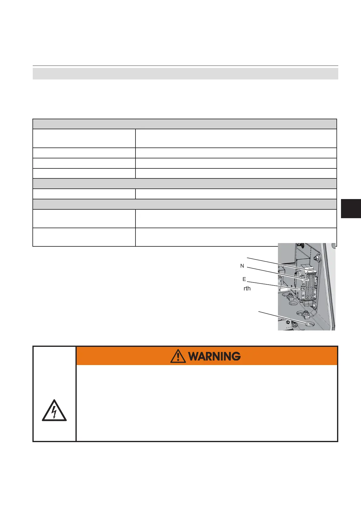
Connecting the power cord
To install the cable proceed according to the
installation instructions for either conduits or
cable glands, given on page 2-11.
Insert the power cord through the foremost
entry, strip the outer insulation, skin and
connect the conductors to the terminals (a
descriptive label is attached nearby the termi-
nals), by inserting them from the bottom sides.
2.4 Installation - Electrical
The power cord is connected to screw-type terminals located inside the housing.
ELECTRICAL SHOCK HAZARD
Verify the power supply at installation site meets the specication given on
the analyzer´s nameplate label, before installing the instrument!
Verify power cables are disconnected and/or instrument is de-energized
prior to working at the terminals!
Verify the power cord is layed with a distance of at least 1 cm (0.5“) to any
signal cable to ensure proper insulation from signal circuits!
Electrical Connections
Power terminals
Schraubklemmen mit integrierten Sicherungshaltern
max. 4 mm²
Supported wire cross sections
0.2 to 4 mm
2
(24 to 12 AWG) no need to use wire end sleeves
Cable skinning length 8 mm (0.315 inch);
Tightening torque, min . 0.5 Nm (4.4 in.lb)
Power Inlet Fuses
Data AC 230 V / T 4 A / 5x20 mm
Cable Inlets
Variations
Cable glandes, IP 68, or
Conduits with adaptors (metric-2-NPT)
Outer cable diameter (cable
glands)
depending on cable gland
Power cord entry
L= Line
N=Neutral
PE=Protective Earth
Fig. 2-14: Power terminals
L
PE
N
 Loading...


