I/O Board Names and Terminology RS485 I/O Network Boards and Peripherals • 2-3
All boards feature both +5VDC and +12VDC output
voltage points for use in powering transducers or other
input devices that require power.
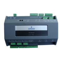
On the RS485 Network, the MultiFlex combination
input/output boards present themselves to site controllers
as 16AI Analog Input Boards, 8RO Relay Output Boards,
8DO Digital Output Boards, and/or 4AO Analog Output
Boards, depending on what type of inputs or outputs are
equipped. Dip switches are used to assign network ID
numbers to each board type.
The MultiFlex combination input/output boards also
support a Hand-held Terminal interface, Section 2.2.7,
Hand-held Terminal (P/N 814-3110) which allows techni-
cians to view input values, check relay and analog output
states, and override output points with fixed digital or ana-
log values. For more information on MultiFlex I/O boards,
refer to the MultiFlex I/O Board Installation and Opera-
tion Manual (P/N 026-1704).
Table 2-2 shows the available models of MultiFlex
combination input/output boards with description and part
numbers.
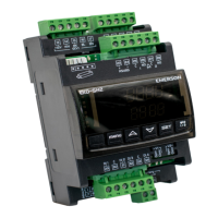
2.2.2 MultiFlex RTU Support
This MultiFlex RTU (Rooftop Unit Board) support
allows you to set the inputs, outputs, setpoints and alarms
on the user interface, and transmit the data through I/O
network between RTU board and Site Supervisor.
2.2.2.1 I/O Network and MultiFlex RTU
Setup on Serial Port
1. Navigate to serial port configuration screen,
select an unused port and configure it as an I/O
network port.
2. Configure the baud rate of the I/O network port,
then select MultiFlex RTU from the supported
board types for this port. Set the number of board
needed to setup, click Save to add the RTU
devices. RTU board status will appear “Online”.
3. Navigate to the “HVAC - RTU_0X” device status
screen through the site map, the status screen dis-
plays the following sections:
• General
• Inputs
• Outputs
• RTU Outputs
4. Click Details on the status screen, the system will
display the properties of the RTU board by the
properties group. You can now view and
configure the properties of the RTU board.
5. After configuring the properties, the new values
can be sent to RTU application on the Site
Supervisor and RTU board on the I/O network.
The RTU board can now work correctly on the
controller.
2.2.2.2 Creating an Instance of RTU
Application
You can create an instance of RTU application even if
the RTU board is not connected to the Site Supervisor
controller, however the board status is displayed “Offline”.
If the RTU board is connected to Site Supervisor
through the I/O network, the Site Supervisor should find
the RTU board and its property values and should be read
on the controller through the I/O network.
2.2.2.3 Deleting/Checking Status of RTU
Board
You can navigate to Network Summary screen to do
the following operations:
1. View all the devices connected to the Site
Supervisor from the I/O network and its online
status.
2. Delete a device.
P/N Model Name Description
810-3063 MultiFlex
88AO
8 analog/digital inputs, 8
relay outputs, 4 analog out-
puts
810-3064 MultiFlex 88 8 analog/digital inputs, 8
relay outputs
810-3065 MultiFlex
168AO
16 analog/digital inputs, 8
relay outputs, 4 analog out-
puts
810-3066 MultiFlex
168
16 analog/digital inputs, 8
relay outputs.
810-3067 MultiFlex
168DO
16 analog/digital inputs, 8
relay outputs, 4 digital out-
puts
810-3072 MultiFlex
1616L
16 analog/digital inputs, 16
low-voltage (24VAC rated)
relay outputs
810-3073 MultiFlex
1616LAO
16 analog/digital inputs, 16
low-voltage (24VAC rated)
relay outputs, and 4 analog
outputs.
810-3077 MultiFlex
1616LDO
16 analog/digital inputs, 16
low-voltage (24VAC rated)
relay outputs, and 4 pulse-
width modulating digital
outputs
Table 2-2 - MultiFlex Combination Input/Output Board Models
 Loading...