5-30 • Site Supervisor Controller User Guide 2.0 026-1800 Rev 3 02-AUG-2016
The following is an example of the application status screen in UltraSite. This property can be added to the Site Super-
visor’s general property.
5.13.3 Inputs
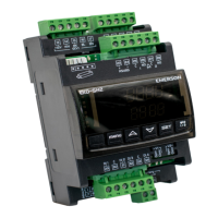
RelayNCommand - The XR75CX CD has four on-
board relays that may be used as satellite outputs by the
other Site Supervisor applications. “RelayNCommand”
can be connected to the output of the other applications
and control other physical device, such as fan and light.
QA can test the output for the corresponding relay and test
the relay output of IPX and Onboard IO.
Digital InputN - The two points show status for the
two digital inputs of XR75CX CD, they can be used as the
output source for pointers.
RelayNFailSafe - The XR75CX-CD can operate in
Normal mode and Standalone (failsafe) mode. When the
case display is communicating normally with the Site
Supervisor, it is operating in Normal mode. If the
communication between the case display and the Site
Supervisor is interrupted, the case display will go into
Standalone (failsafe) mode. The value of Realy1FailSafe
could be tested by the value of the corresponding relay in
Standalone mode.
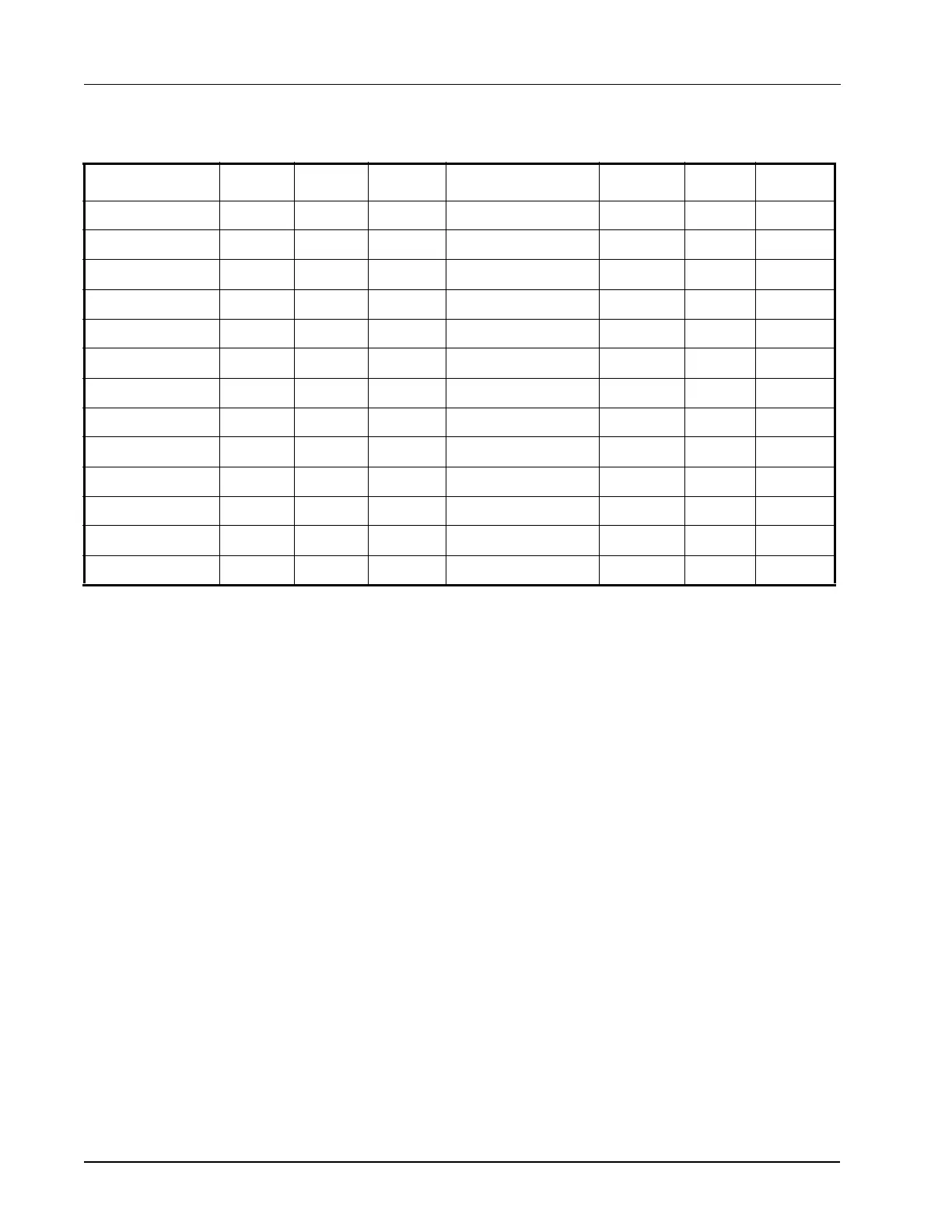
Input Property: Value: Units: Status: Output Property: Value: Units: Status:
COMM STATUS No Port NA
DISPL TEMP NONE DF NA
DISCHARGE AIR NONE DF NA
PRODUCT TEMP NONE DF NA
COIL OUT TEMP NONE DF NA
DEFROST TEMP NONE DF NA
DIGITAL INPUT2 NOTACT DIG NA
RELAY 1 STATE NOTACT DIG NA
RELAY 2 STATE NOTACT DIG NA
CD ALARM OUT NOTACT DIG NA
RELAY 3 STATE NOTACT DIG NA
RELAY 4 STATE NOTACT DIG NA
EEPROM ALARM NOTACT DIG NA
Table 5-11 - XR75CX Case Display Status Screen Properties