Analog Sensor Control Software Overview • 5-3
5.2 Analog Sensor Control
The Analog Sensor Control reads the values from one
or more analog sensors, compares them to a set of Cut In/
Cut Out setpoints, and operates a digital output (such as a
relay) based on the analog input in relation to the
setpoints.
An Analog Sensor Control module performs three
functions:
• COMBINER - Up to four analog inputs are
combined into a single analog value.
• CUT IN/CUT OUT CONTROL - The combined
input value is compared to a Cut In/Cut Out
setpoint. Based on this comparison, a digital output
will be turned ON or OFF.
• ALARMING - Alarms and notices can be
generated based on the combined value of the
inputs and its relation to a set of high and low alarm
and notice setpoints.
5.2.1 Control Strategy
The application combines multiple analog inputs into a
single output, using either the primary combination
method or the alternate combination mode, depending on
the state of the Use Alternate Combination property.
The primary and alternate combination methods may
be configured to be one of the following:
• Average - of all defined inputs
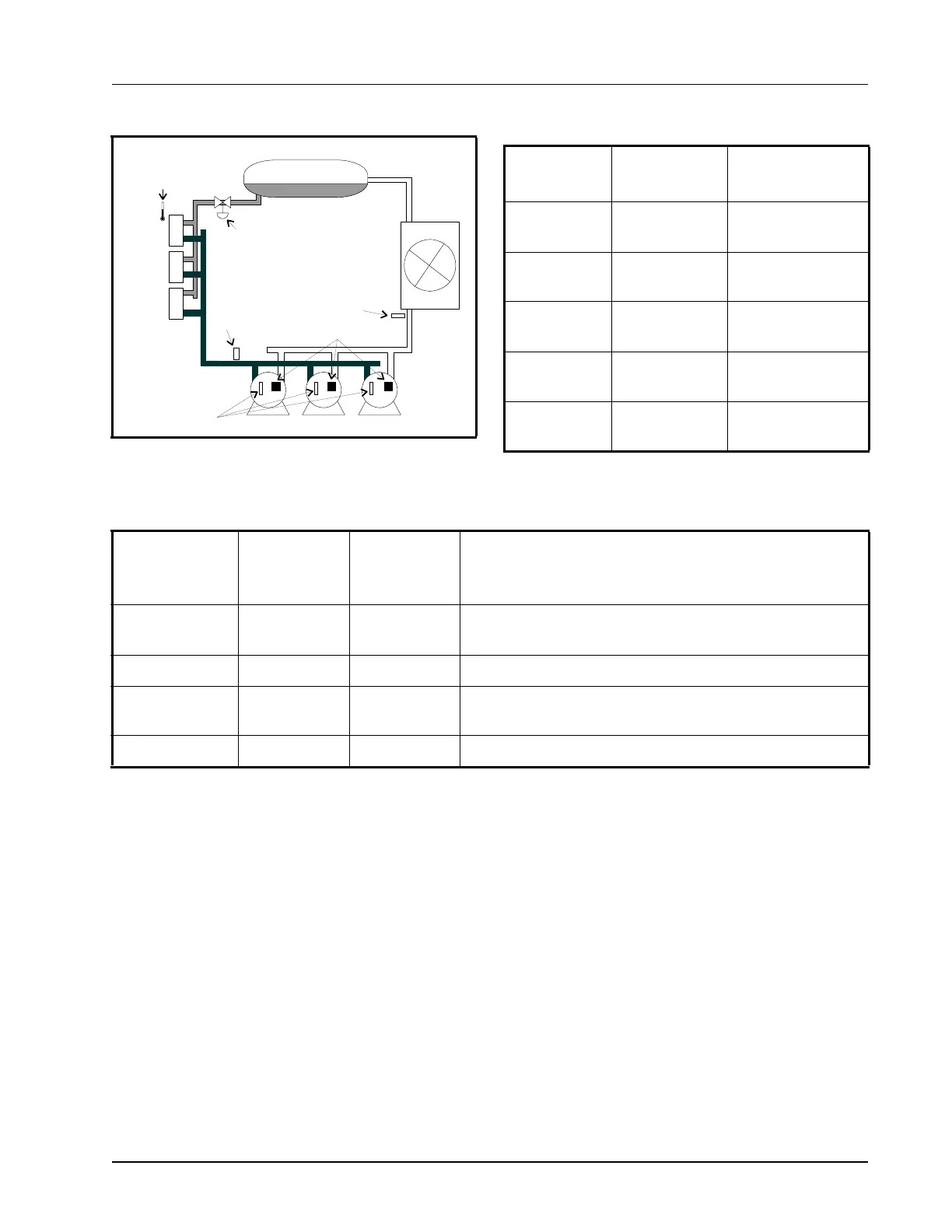
Figure 5-1 - Diagram of a Suction Group
DISCHARGE
PRESSURE
LIQUID RECEIVER
CASE CIRCUIT
OIL
PRESSURE
CIRCUIT
CASE TEMP
(FOR FLOATING)
LIQUID LINE
SOLENOID
26507005
DDD
OIL RESET SWITCHES
Input Sensor Type
Wiring
Instructions
Suction
Pressure
100 lb. Eclipse
transducer
(see Table 9-1 on
page 9-3)
Discharge
Pressure
500 lb. Eclipse
transducer
(see Table 9-1 on
page 9-3)
Oil Pressure
200 lb. Eclipse
transducer
(see Table 9-1 on
page 9-3)
Case Circuit
Temperature
Temperature
(see Table 9-1 on
page 9-3)
Oil Reset
Switches
Digital
(see Table 9-1 on
page 9-3)
Table 5-1 - Suction Group Inputs
Output Device
Wire Output
Board
Contacts to:
Set Failsafe
Dip Switch
to:
Notes
Compressor N.C. N.C. (up)
If you want a compressor to be OFF during network/power
loss, use N.O. fail-safes instead.
Unloader N.C. N.O. (down) These fail-safe settings are specifically for unloaders.
Liquid Line
Solenoid (LLS)
N.C. N.C. (up) Keeps solenoid energized during network/power loss.
Electric Defrost N.O. N.O. (down) Keeps contacts de-energized during network/power loss.
Table 5-2 - Suction Group Outputs