Installation and commissioning PlasmaQuant 9100 (Elite)
34
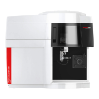
Figure18Connection panel on the right side of the sampler
1 DIP switch 2 "HOST" connection (to the basic de-
vice)
3 Power switch 4 Fuse holder
5 Power connection
Note: DIP switch 5 is set to "ON".
Only the aforementioned connections are required for the use of the sampler together
with the basic device. All other connections and displays are for service purposes or not
in use.
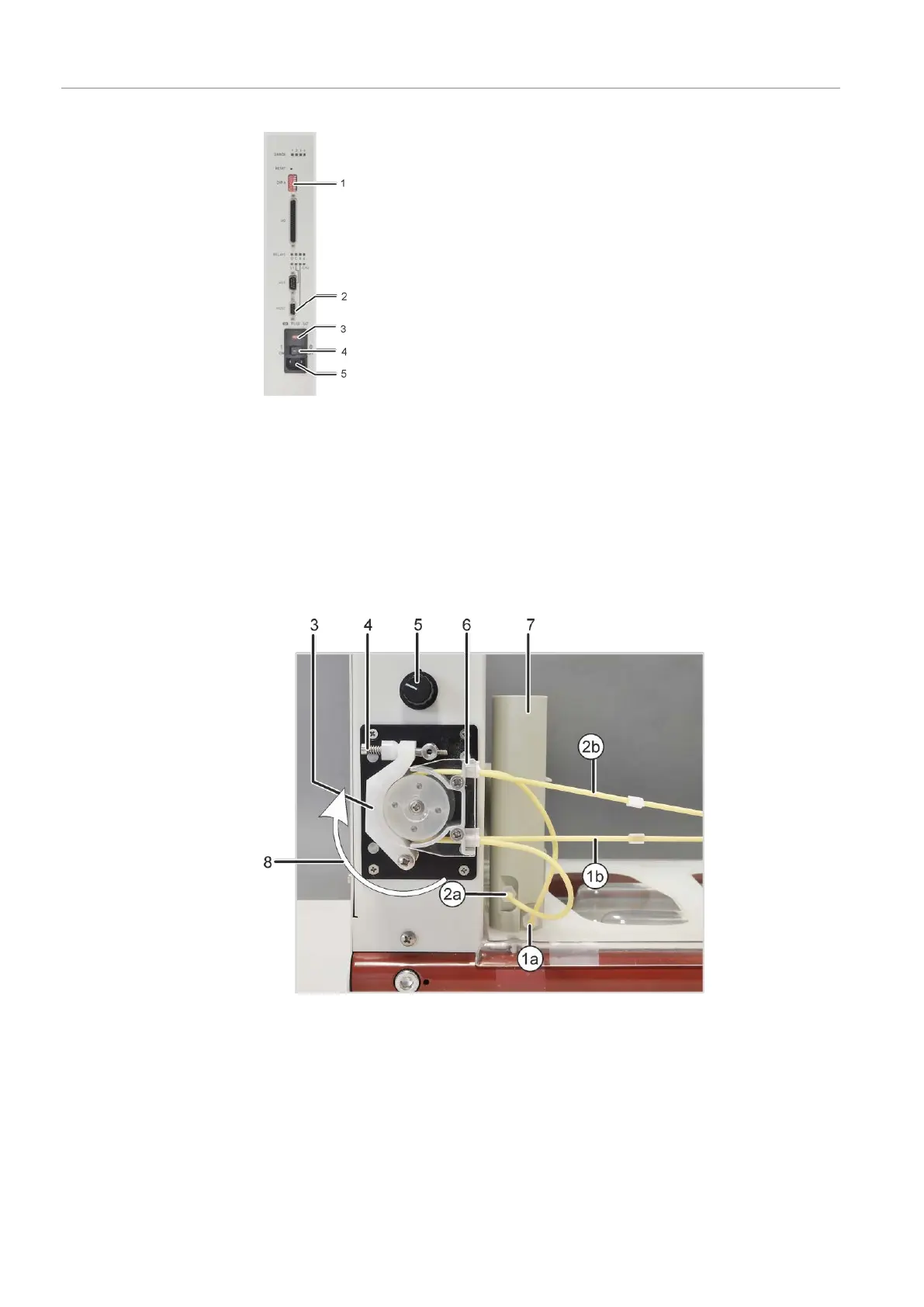
Figure19Purging vessel and pump on the sampler
1a Intake connection for purging solu-
tion on the purging vessel
1b Purging solution hose
2a Waste connection on the purging
vessel
2b Hose to the waste container
3 Clamping bracket 4 Clamping lever with spring
5 Pump speed controller 6 Hose block for clamping the pump
hoses
7 Purging vessel 8 Pump direction
 Loading...


